dces
Controlled Stirling Thermocompressors
This project focuses on research towards the improvement, modeling, and experimental testing of Stirling engines.
A Stirling engine is a heat engine that can operate using a variety of heat sources such as high energy density hydrocarbon fuels (propane, butane, natural gas, etc), waste heat, solar concentrators, geothermal, radioisotope source, or others.
The Stirling engine was invented by Robert Stirling in 1816. It consisted of a sealed engine section, a displacer piston, and a power piston. The displacer piston separates the hot and cold side. Historically displacer piston and power piston were kinematically linked.
While the historical Stirling engines where the displacer piston and power piston were kinematically linked was too bulky and heavy to produce much power, free-piston Stirling engines use dynamic arrangements to achieve the correct phase between displacer and power piston. Even tough free-piston Stirling engines are much lighter and more compact; they have to robustly maintain self-oscillation in the face of load variation and disturbances. Since this is very hard to achieve, this project overcomes the difficulty of achieving the correct phase dynamically by directly controlling the motion of the displacer piston (see schematic Fig. 1). By independently driving the displacer, the motion of the displacer is decoupled from the pressure dynamics within the engine. By decoupling the displacer motion and then controlling it independently, the load does not affect the engine’s ability to self-oscillate. This additional control degree of freedom allows an independent design of the displacer piston motion that can be controlled to shape the thermodynamic cycle in the face of arbitrary loads.
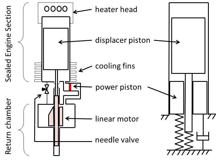
Figure 1 shows a schematic of the first prototype of the Stirling device on the left. The sealed engine section has a hot (towards the heater head) and a cold side (towards the cooling fins) which are separated by the displacer piston. The displacer is actuated with a linear motor which is located in the return chamber. Helium is used as the working fluid for this device since helium has very good heat transfer properties. The sealed engine section and return chamber are connected via a needle valve. The needle valve represents a flow restriction which guarantees an average pressure in the return chamber. When the displacer is moved up and down the engine section, the working fluid is shuttled from the hot to the cold and from the cold to the hot side. The resulting temperature change of the working fluid (helium) produces a pressure oscillation inside the engine section. The pressure difference between the average pressure in the return chamber and the oscillating pressure in the engine section can then be used to drive a power piston. This power piston could represent a linear electric generator, a hydraulic pump, a compressor, among others. This project is supported by the Center for Compact and Efficient Fluid Power, an NSF Engineering Research Center.
Publications
©2024 Vanderbilt University ·
Site Development: University Web Communications