Serial Output for Myoware Sensors
First Visualization of Myoware Sensors
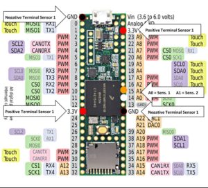
The relative ports for each of the myoware input/outputs for serial observation of the output forms. This is without internal feedback, that is each sensor is outputting to independent analog ports to be read. Theoretically, both sensor positive nodes could be soldered to the same 3.3 V node in the future, the same with the ground outputs. The myoware also have ‘Raw’ ports that can allow visualization of EMG outputs before processing within the board. These should be placed in A2 and A3 respectively for each of the two sensors.
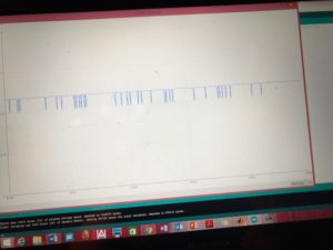
Arduino serial plotter was used for visualizing the data, the blue line is always Analog 0 outputs as can be seen in a signal image below and a read line appears as the output for Analog 1 inputs. This code will not be used in final product, but rather for all experiments regarding EMG signal observations.
Good Resources for Initial EMG output to Arduino platform
- http://www.theorycircuit.com/myoware-muscle-sensor-interfacing-arduino/
- https://www.oreilly.com/library/view/arduino-cookbook/9781449399368/ch04.html
- https://www.norwegiancreations.com/2016/01/tutorial-multiple-values-in-the-arduino-ide-serial-plotter/