1/16/2020 Infrared CT Update #2
Antonio Glenn, Hannah Kilpatrick, Danielle Liu
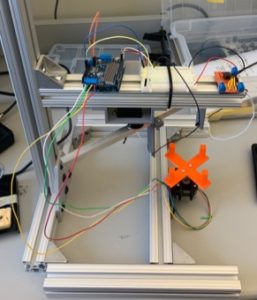
This week, we finished building our two circuits and attached them to our IR CT scanner using velcro. The photodiode in the circuit was oriented so the long leg was closer to the power supply so that we read a positive output voltage. Using the data sheet of the op amp, we calculated that when the LED and photodiode were 10 cm apart, a 300 ohm feedback resistor would use the most Arduino input range between light and dark states of the LED.
Next, we programmed the Arduino to measure analog input from the photodiode circuit and output the values in Matlab. This allows us to collect all our data through Arduino and then process the signal in Matlab. We also began programming the Arduino to move the stepper motors, which is shown in the video below.
Below is an image of our IR CT scanner with the circuits attached to the frame with velcro. The left circuit powers the emitter and the right circuit powers the detector.

Link to video of stepper motors: IMG_9876
Arduino code for controlling stepper motors and reading photodiode data:
#include <Wire.h>
#include <Adafruit_MotorShield.h>
//#include <Adafruit_PWMServoDriver.h>
// Create the motor shield object with the default I2C address
Adafruit_MotorShield AFMS = Adafruit_MotorShield();
// Or, create it with a different I2C address (say for stacking)
// Adafruit_MotorShield AFMS = Adafruit_MotorShield(0x61);
// Connect a stepper motor with 200 steps per revolution (1.8 degree)
// to motor port #2 (M3 and M4)
Adafruit_StepperMotor *myMotor = AFMS.getStepper(200, 2);
//Photodiode
int sensorPin = A0;
int sensorValue = 0;
void setup() {
Serial.begin(9600); // set up Serial library at 9600 bps
pinMode(sensorPin, INPUT);
AFMS.begin(); // create with the default frequency 1.6KHz
//AFMS.begin(1000); // OR with a different frequency 1KHz
myMotor->setSpeed(10); // 10 rpm
}
void loop() {
Serial.println(“Single coil steps”);
myMotor->step(100, FORWARD, SINGLE);
myMotor->step(100, BACKWARD, SINGLE);
}
