Authors: Nicholas J. Holden and Javier
This week we were able to successfully build a working current-to-voltage circuit and get it working with both the photodiode and LED connected to the device. We determined the problem was with the photodiode which we suspect burned out during soldering. After replacing the photodiode, we were able to receive voltage measurements from the LED and photodiode.
After completing this part of the build, we directed our attention to the servo. Our goal was to get it to rotate 180 degrees from the left and from the right. We encountered challenges from the Arduino Adafruit shield which had several ports that didn’t function. Once resolving this issue, we used code from last week to get the servo motor to rotate properly. We also finished porting of the Arduino data to Matlab allowing for the gathering of data from the device to be processed in Matlab. The code shown below opens a serial port and waits for a start and end string that allows it to read the data in between the start and endpoints.
The next steps for this project are to consolidate the device to be more aesthetically pleasing and efficient with space. We will accomplish this by attaching the Arduino and breadboard to a metal beam above the servo. We also need to start writing the code for the processing of slices in Matlab as getting the rotation of the stepper motor to work and connected to the Arduino.
Question: How can you limit the current to avoid damaging the LED in the output?
Answer: Place a current limiting resistor between the LED and the 5V pin to avoid overloading the LED.
Question: Does the value of the current-limiting component affect the amount of light you detect with the photodiode? Can you optimize that?
Answer: The resistor does take away some of the voltage from the LED that can make the LED less bright. However, the LED is maximally powered at 1.2V, and the current drawn from the Arduino is around 20mA. This means the resistor should draw 3.8V which relates to 190 Ohms of resistance based on the current from the Arduino. This would prevent the burning of the LED without reducing brightness.
% open the serial port
s = serial(‘/dev/cu.usbmodem14401′,’Baudrate’,14400);
fopen(s);
% initializing variables
stepAngle = [];
servo_us = [];
servoAngle = [];
potVoltage = [];
diodeVoltage = [];
% listen for the begin statement
readString = ‘foo’;
while isempty(strfind(readString,’Start’))
readString = fscanf(s);
end
disp ‘acq started!’
% read data until the end statement
while isempty(strfind(readString,’End’))
readString = fscanf(s);
if isempty(strfind(readString,’End’))
% parse the string for data
C = strsplit(readString,’,’);
stepAngle(end+1) = str2num(C{1});
servo_us(end+1) = str2num(C{2});
servoAngle(end+1) = str2num(C{3});
potVoltage(end+1) = str2num(C{4});
diodeVoltage(end+1) = str2num(C{5});
% report progress
if ~rem(length(stepAngle),100) disp(sprintf(‘Stepper angle: %d’,stepAngle(end))); end
end
end
disp ‘acq ended!’
% save the data
save data_phantom_19200 stepAngle servo_us servoAngle potVoltage diodeVoltage
% close the serial port
fclose(s);
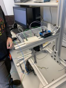
Picture 1: The photo demonstrates the ideal placement of the Arduino and the breadboard. As you can observe, the length of the wires are too long and need to be shortened.
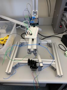
Picture 2: This picture not only offers another perspective but allows the viewer to see the artifact.