
CT Scanner Blog Post Week #2
Aayush Gupta and Hunter Spivey
This week we were able to successfully design and implement a circuit that is used to power the IR LED using the Arduino Uno’s 5V supply. Moreover, we were able to incorporate a current-to-voltage op amp circuit that converts the photodiode current into a voltage signal, which is then sampled through the Arduino. We were able to ascertain that the current-to-voltage circuit was working properly by covering and uncovering the photodiode when the system was hooked up and then by discerning, through the use of a multimeter, that when it was covered the voltage values printed on Arduino were significantly lower (0-0.5V) than those when it was left uncovered (4.3-4.5V).
In the following week we will focus on programming the Arduino to move the stepper motor and server across a certain range, as well as collecting the position versus photodiode voltage data as it moves. We will also look into producing the MATLAB script that reads the Arduino’s serial port and records the values that it receives.
Image #1: This image shows the current-to-voltage and Arduino receptor circuits optimally set up.
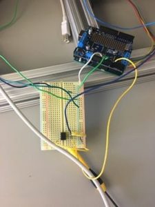
Image #2: This image exhibits the Arduino code needed to correctly print the voltage outputted from the op amp circuit.

Below are the answers to the questions for this week:
Question: How can you limit current into the LED to avoid damaging it?
We limited the current into the LED to avoid damaging it by inserting a current loading pin in the circuit, placed between the 5 volt output and the LED, this caused the LED to not have too much current flowing into it and remains usable.
Question: Does the value of the current-limiting component affect the amount of light you detect with the photodiode? Can you optimize that?
The value of the current-limiting resistor does affect the amount of light that is detected by the photodiode, with the presence of a higher resistor causing a less luminescent lightbulb. This can be optimized by taking into account the voltage needed to power the lightbulb and using that value figuring out what the voltage across the current-limiting resistor should be. By using that voltage and the current from the Arduino, we can easily deduce the optimal resistance value of the component.