
Morgan Kinney, Tanner Hoppman, Jude Franklin
This week we were able to continue troubleshooting our circuits. By using a multimeter, we were able to determine if the voltage at the input and outputs of the circuit was reactive to the LED and IR photodiode (Element 1). Initially, we had the setbacks of the IR LED being shortcircuited, thus we had to re-solder the connections. After we were able to determine a proper relationship between the distance between the photodiode and the LED and their relative output voltage by changing our feedback resistor to a megaohm, we focused on uploading Arduino code to read the analog input and translate that into the Serialread function. Thus, we were able to see the live read-outs of the voltage values on the serial monitor as the IR LED and photodiode distance changed. We left off attempting to transfer the serial monitor values into Matlab where they will be much more useful for image reconstruction (Element 2).
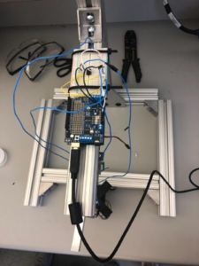
Element 1: Placement of the breadboard and Arduino on the frame. This location will allow for the circuits to remain intact while the servo arm moves during image acquisition.
Element 2: Arduino and Matlab code used to communicate serial port data with Matlab.
Arduino code:
byte incomingByte1;
void setup(){
pinMode(2,OUTPUT);
Serial.begin(115200);
Serial.println(“Ready”);
}
void loop() {
digitalWrite(2,LOW); //turn off LED
delay(500);
if (Serial.available() > 0) {
digitalWrite(2,HIGH); //flash LED everytime data is available
delay(500);
incomingByte1 = Serial.read(); //read incoming data
Serial.println(incomingByte1,HEX); //print data
}
}
Matlab code:
clear
clc
s=serial(‘COM7’,‘BaudRate’,115200);
fopen(s);
readData=fscanf(s) %reads “Ready”
writedata=uint16(500); %0x01F4
fwrite(s,writedata,‘uint16’) %write data
for i=1:2 %read 2 lines of data
readData=fscanf(s)
end
fclose(s);
delete(s);
Question: How can you limit current into the LED to avoid damaging it?
Answer: By connecting a resistor in series with the LED and the Arduino power source, the current of the total circuit is reduced, which decreases the chances of damaging the LED. This does, however, decrease the voltage drop across the LED, which decreases its brightness, but using a moderately low resistor value (1kOhms) allows this effect to be minimal.