Javier and Nicholas J. Holden
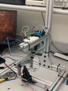
This week, we tried to make our work more aesthetically pleasing and efficient by securing the wires as well as both the breadboard and Arduino to the metal bar above the servo. The breadboard was fashioned with a double-sided adherence tape and the Arduino was with Velcro. This allows the ability to attach and detach the Arduino which is useful. In addition, many wires were shortened and also shrinking tape was attached to the various junctions to not leave those connections exposed.
We encountered the problem of the servo shaking in place and not moving. The problem was solved by reworking part of the code written for it and moving a pin to a different analog input. It now works as intended; however, as one problem ends, another begins. The stepper is our primary challenge. While all the correct wires are attached to our Arduino, the code is not allowed to run. Many solutions were attempted such as just moving utilities into the folder to allow the code to work as well as running the test code. In a desperate attempt, we disconnected our servo from our stepper. With this connection severed, the stepper began to rotate as programed below. It was concluded that for some reason our servo was interfering with our stepper. The working theory is that the servo may be drawing too much current. Our solution was to install a new servo and see if that will work. But before that solution was carried out, we noticed that the servo control wire may be stealing tons of current. So we attempted to resolder and attach the control wire back into the 3 pin set up because the control wire wasn’t connected to the power wires. This did not work, so the original solution to replace the servo was taken. \
Unfortunately, when we added the new servo, we encountered the same problem again: the stepper stopped rotating. Our next idea was to restart the Arduino. This still did not fix anything. In an absolutely desperate attempt, we had to use a different pin for our potentiometer from the servo. That was the problem. However, this solution broke the servo. We believe the same issue is at play though and so only need to find another analog pin to get the system to work.
Below are an attached photo and video of the updated machine. Photo 1 is a picture of the current system. There is a marked improvement to the design compared to last week. Video 1 displays the servo and stepper in action. After many weeks, we have finally achieved the desired function from both of the devices. Our next steps are to fine-tune the system and create MATLAB code to be able to do reconstruction for the information collected from the photodetector as well as fine-tune the Arduino code for this same process. The Arduino code needs to be updated to better replicate the fan angle as well as provide measurements for each of the fan angle.
Below is our code for the Servo motor and the Stepper
#include <Servo.h>
#include <Wire.h>
#include “utility/Adafruit_MS_PWMServoDriver.h”
#include <Adafruit_MotorShield.h>
int servopin = 9;
Servo servo;
int angle =0;
// Create the motor shield object with the default I2C address
Adafruit_MotorShield AFMS = Adafruit_MotorShield();
// Connect a stepper motor with 200 steps per revolution (1.8 degree)
// to motor port #2 (M3 and M4)
Adafruit_StepperMotor *myMotor = AFMS.getStepper(200, 2);
void setup() {
// put your setup code here, to run once:
Serial.begin(9600);
servo.attach(servopin);
AFMS.begin(); // create with the default frequency 1.6KHz
myMotor->setSpeed(60); // 10 rpm
}
void loop() {
// put your main code here, to run repeatedly:
for(angle=70; angle<230; angle++){
servo.write(angle);
double sensorvalue = analogRead(A2);
double pot = analogRead(A3);
Serial.print(sensorvalue/1023*5);
Serial.print(“,”);
Serial.println(pot/1023*5);
myMotor->step(50, FORWARD, MICROSTEP);
delay(50);
}
for(angle=230; angle>70; angle–){
servo.write(angle);
double sensorvalue = analogRead(A2);
double pot = analogRead(A3);
myMotor->step(50, FORWARD, MICROSTEP);
Serial.print(sensorvalue/1023*5);
Serial.print(“,”);
Serial.println(pot/1023*5);
delay(50);
}
delay(1000);
}

Photo 1 – Improved CT System
Please click the link to the right to watch the video of the CT Stepper in action – IMG_1004
Question: Which way does your photodiode need to be oriented to get a positive output voltage?
Answer: In order for the photodiode to receive a positive output voltage, it needs to be oriented so that the cathode is facing the op-amp, and the anode is facing ground. You will get a positive voltage that way.
