IR CT Scanner Week 2

Alex Boyd, Maggie Ford, Myron Mageswaran

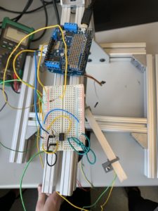
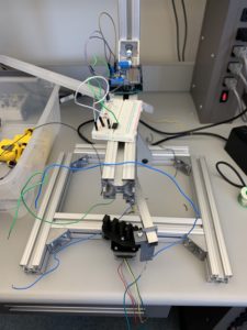
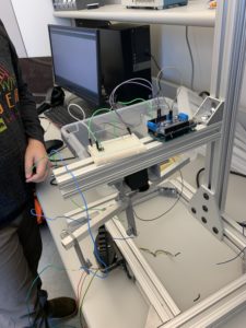
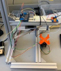
Because we previously finished our current to voltage op amp circuit, we spent a majority of our time this week programming the Arduino to move the stepper motor and servo.  We were then able to report the servo and stepper positions to the serial monitor along with the voltage output. We programmed the motors such that the servo with the IR LED and photodiode fans across the object that is being imaged and then returns to its initial position. Once the servo finishes fanning across the object, the stepper motor rotates a specified range to prepare a new view for the next time the servo fans across the object.

Next week, our focus will be to read the Arduino’s serial output using MATLAB (voltage and motor positions) in order to reconstruct our data into images. We also need to fine tune how much the stepper motor rotates each time the servo fans over the object in order to maximize spatial resolution.

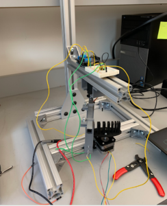
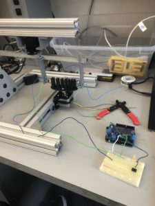
Video 1:  This video shows the servo sweep the IR diode across the object that is being scanned, return the IR diode to its initial position, the stepper rotate the object a small amount, and the process repeats.  

Arduino Servo and Stepper Moving

Matlab Code: This is the code we have written to read the Arduino’s serial output and store the data as a matrix in Matlab. So far, we have only written code to read the voltage output, but we will add to the code to include motor positions as well.

% create arduino object

a = arduino(‘port’,‘board’);

% create time vector

v = zeros(500,1);

t = seconds(v);

t0 = datetime(‘now’);

% enter voltage readings into a vector as time elapses

for ii = 1:length(v)

    v(ii) = readVoltage(a,‘pin’);

    t(ii) = datetime(‘now’) – t0;

end

Question: The servo has an extra (white) wire on it, that reads out its built-in position potentiometer, which you can use to record the servo’s actual position (rather than just its intended position). Is your image reconstruction improved by using this value instead of the intended value?

Answer: Using the actual position output from the servo does not improve the image reconstruction because these values are no different than the servo’s intended position.  Therefore, we will utilize the servo’s intended position values for our purposes of this scanner.

Question: Why is the Matlab function fan2para() function needed?

Answer: The fan2para() function in Matlab is needed to convert the fan-beam projections into parallel-beam projections because the IR CT scanner has a fan-beam geometry, but filtered backprojection algorithms require parallel-beam geometry.

CT Scanner Update 2

Blog Post Week #2: Imaging Instrumentation Infrared CT Lab
Jorie Budzikowski, Stephanie Molitor, and Rachel Welscott

(overheard) QUOTE OF THE WEEK:
“You know I am just really skeptical because Dr. Grissom DID NOT say to do that.”

This week we made significant progress on our CT scanner. We completed the circuit elements of our CT scanner including the IR LED and the photodiode circuits shown in Image 1 below. Using a multimeter, were able to verify that our circuit was working correctly such that the output voltage decreased when the path between the IR emitter and the photodiode was blocked. We tuned our feedback resistor value to get readout voltages in the desired range (2-3 V with full IR exposure). We then were able to program our Arduino to report the proper output voltage value on the serial monitor. A video of this Arduino readout is shown in the first video below.

Image One: The complete IR LED and photodiode circuits attached to the Arduino Uno that provides the power to the circuits.
46B5B08B-8150-4540-8548-59CC16BD8E49


Image Two: The Arduino code that prints the output voltage from the above circuit.

arduino LED code


Video One: The display of output voltage from the photodiode is shown on the serial monitor of the Arduino. When the photodiode is uncovered, the voltage is around 3 V. When the photodiode is covered, the voltage values are around 0V.


Questions we set out to answer this week:

    • Question: What does the datasheet say to do with the unused amp on your chip? Does doing this affect your images in any way?
      • The unused amp pins are all connected to ground. This has allowed a current to voltage conversion in our circuit, but we have yet to actually collect any images.
    • Question: What does the datasheet say about the maximum voltage you can get out of the op amp? What is the max voltage you actually get?
      • The datasheet says that  the maximum rail (V_DD) voltage that op amp can handle is 5V. This implies that the maximum voltage that you can get out of the op amp is 5V. However, the datasheet also lists the minimum and typical high-level output voltages for the op amp as 3.2 V and 3.8 V, respectively. The datasheet does not list the maximum high-level output voltage.
      • The max voltage that we were able to measure from the op amp was 3.6 V.
    • Question: Can you optimize the value of the feedback resistor to use as much of the Arduino’s input range as possible, between light and dark states, when the LED and photodiode are set 10 cm apart in their holders?
      • We were able to optimize the value of the feedback resistor by choosing a 4.7 megaOhm resistor. This allowed us to reach approximately 3.5 V maximum when the LED was uncovered and 0 V minimum when the LED was covered.

CT Scanner Week #2 -1/17/2020

Authors: Nicholas J. Holden and Javier

This week we were able to successfully build a working current-to-voltage circuit and get it working with both the photodiode and LED connected to the device. We determined the problem was with the photodiode which we suspect burned out during soldering. After replacing the photodiode, we were able to receive voltage measurements from the LED and photodiode. 

After completing this part of the build, we directed our attention to the servo. Our goal was to get it to rotate 180 degrees from the left and from the right. We encountered challenges from the Arduino Adafruit shield which had several ports that didn’t function. Once resolving this issue, we used code from last week to get the servo motor to rotate properly. We also finished porting of the Arduino data to Matlab allowing for the gathering of data from the device to be processed in Matlab. The code shown below opens a serial port and waits for a start and end string that allows it to read the data in between the start and endpoints. 

The next steps for this project are to consolidate the device to be more aesthetically pleasing and efficient with space. We will accomplish this by attaching the Arduino and breadboard to a metal beam above the servo. We also need to start writing the code for the processing of slices in Matlab as getting the rotation of the stepper motor to work and connected to the Arduino. 

Question: How can you limit the current to avoid damaging the LED in the output?

Answer: Place a current limiting resistor between the LED and the 5V pin to avoid overloading the LED.

Question: Does the value of the current-limiting component affect the amount of light you detect with the photodiode? Can you optimize that?

Answer: The resistor does take away some of the voltage from the LED that can make the LED less bright. However, the LED is maximally powered at 1.2V, and the current drawn from the Arduino is around 20mA. This means the resistor should draw 3.8V which relates to 190 Ohms of resistance based on the current from the Arduino. This would prevent the burning of the LED without reducing brightness.

% open the serial port

s = serial(‘/dev/cu.usbmodem14401′,’Baudrate’,14400);

fopen(s);

% initializing variables

stepAngle = [];

servo_us = [];

servoAngle = [];

potVoltage = [];

diodeVoltage = [];


% listen for the begin statement

readString = ‘foo’;

while isempty(strfind(readString,’Start’))

    readString = fscanf(s);

end


disp ‘acq started!’


% read data until the end statement

while isempty(strfind(readString,’End’))

    readString = fscanf(s);

    if isempty(strfind(readString,’End’))

        % parse the string for data

        C = strsplit(readString,’,’);

        stepAngle(end+1) = str2num(C{1});

        servo_us(end+1) = str2num(C{2});

        servoAngle(end+1) = str2num(C{3});

        potVoltage(end+1) = str2num(C{4});

        diodeVoltage(end+1) = str2num(C{5});

        % report progress

        if ~rem(length(stepAngle),100) disp(sprintf(‘Stepper angle: %d’,stepAngle(end))); end

    end

end


disp ‘acq ended!’


% save the data

save data_phantom_19200 stepAngle servo_us servoAngle potVoltage diodeVoltage


% close the serial port

fclose(s);


Picture 1: The photo demonstrates the ideal placement of the Arduino and the breadboard. As you can observe, the length of the wires are too long and need to be shortened. 

IMG_0968 copy

Picture 2:  This picture not only offers another perspective but allows the viewer to see the artifact.

IMG_0967 copy

1/16/2020 Infrared CT Update #2

1/16/2020 Infrared CT Update #2

Antonio Glenn, Hannah Kilpatrick, Danielle Liu

This week, we finished building our two circuits and attached them to our IR CT scanner using velcro. The photodiode in the circuit was oriented so the long leg was closer to the power supply so that we read a positive output voltage. Using the data sheet of the op amp, we calculated that when the LED and photodiode were 10 cm apart, a 300 ohm feedback resistor would use the most Arduino input range between light and dark states of the LED.

Next, we programmed the Arduino to measure analog input from the photodiode circuit and output the values in Matlab. This allows us to collect all our data through Arduino and then process the signal in Matlab. We also began programming the Arduino to move the stepper motors, which is shown in the video below.

Below is an image of our IR CT scanner with the circuits attached to the frame with velcro. The left circuit powers the emitter and the right circuit powers the detector.

Picture1

Link to video of stepper motors: IMG_9876

Arduino code for controlling stepper motors and reading photodiode data:

#include <Wire.h>
#include <Adafruit_MotorShield.h>
//#include <Adafruit_PWMServoDriver.h>

// Create the motor shield object with the default I2C address
Adafruit_MotorShield AFMS = Adafruit_MotorShield();
// Or, create it with a different I2C address (say for stacking)
// Adafruit_MotorShield AFMS = Adafruit_MotorShield(0x61);

// Connect a stepper motor with 200 steps per revolution (1.8 degree)
// to motor port #2 (M3 and M4)
Adafruit_StepperMotor *myMotor = AFMS.getStepper(200, 2);

//Photodiode
int sensorPin = A0;
int sensorValue = 0;

void setup() {
Serial.begin(9600); // set up Serial library at 9600 bps
pinMode(sensorPin, INPUT);

AFMS.begin(); // create with the default frequency 1.6KHz
//AFMS.begin(1000); // OR with a different frequency 1KHz

myMotor->setSpeed(10); // 10 rpm

}

void loop() {
Serial.println(“Single coil steps”);
myMotor->step(100, FORWARD, SINGLE);
myMotor->step(100, BACKWARD, SINGLE);
}

Infrared CT Update 1: January 14, 2020

Morgan Kinney, Tanner Hoppman, Jude Franklin

This week we were able to obtain our photodiode and infrared LED and secure them into their holders. We soldered lead wires to the ends of each of these to eventually connect them to the Arduino. To power the IR LED, we designed a simple circuit using the Arduino’s 5 volt power source connected in series to the LED and a resistor to decrease the current through the LED and avoid damaging it. 

The image below shows our initial attempt at building the photodiode circuit, which is a current-to-voltage converter taking the input current from the photodiode and outputting a voltage through the TLV2322 op amp to be read by the Arduino.

Our next steps will involve optimizing the outputs of both the LED and the photodiode to obtain the best possible data. This will require tweaking of the resistor values in both circuits and evaluating the voltage outputs when the LED and photodiode are at their 10 cm set distance.

Screen Shot 2020-01-14 at 11.13.24 AM

Infrared CT Scanner Week 1

Alex Boyd, Maggie Ford, Myron Mageswaran

During the first week the group soldered wires to the photodiode and IR LED and constructed the LED driving circuit along with the photodiode circuit to voltage conversion circuit.  The group was able to read voltages using the arduino serial monitor and will now proceed to interfacing the serial monitor with matlab as well as creating code to control the servo motor and stepper motor.

Attached is a picture of the circuit diagram used to construct the current to voltage conversion circuit for input into the arduino.

IR CT Scanner Current to voltage circuit diagram

Blog Post Week #1: Imaging Instrumentation Infrared CT Lab

Jorie Budzikowski, Stephanie Molitor, and Rachel Welscott

This week we designed a two circuits, one to power the Infrared LED and the second to amplify the signal received by the photodiode. We also began to test the signal from the IR to the photodiode and physically implemented both of these circuits onto the servo itself. Our designed circuit consists of two parts, the first of which is an infrared LED circuit. The IR LED is powered by a 5 V supplied by the Arduino Uno. A resistor separates the LED from the power supply to ensure that too much voltage is not applied across the LED damaging it. The second half of the circuit is a current-to-voltage converter. The photodiode receives light emitted from the IR LED, which results in a current output from the photodiode. This current is directed into the positive terminal of the op amp. The noninverting op amp has a feedback resistor that amplifies this input and results in an output voltage proportional to the current supplied by the photodiode. This essentially converts the IR from the LED to voltage that can be recorded by the Arduino.

The circuit design on our breadboard and Arduino is as shown in the schematic below:

blog post 1

The circuit diagram implemented onto the breadboard and the Arduino:

blog 1.1

Finally, the entire servo, circuit, Arduino, and phantom together:

blog 1.2

Next week, we will continue to finalize the circuit design and program the Arduino to communicate with the servo.

1/9/20 Project Update #1

Ganesh, Javier, Nicholas J. Holden (pen name)

This week we finished soldering the leads from the LED diode and Photodiode to wires. We initially encountered errors with soldering, but this was resolved by changing the soldering iron. We designed and built the current-to-voltage circuit as well as the current limiting circuit for the LED. We have encountered errors in this process as when ported to Arduino the values showed no changes in the voltages regardless of distance between the LED and photodiode. We tried to solve this issue by changing the amplification of the current-to-voltage circuit, but this didn’t yield any results.

The code below was an attempt to gather data as the arm sweeps. We simplified the code without the porting to Matlab and getting rid of the sweeping to test the circuit. We are planning to get the servo motor to sweep and also fix the current-to-voltage converter till we can see a measurable change in the voltage based off distance. We are also planning to start writing the Matlab code to read the serial data.
int servoPin = 9;

Servo servo;

int angle = 0; // servo position in degrees

void setup() {
// sets up serial ports and output pins
Serial.begin(9600);
servo.attach(servoPin);
}

void loop() {
//starts a data collection
Serial.println(“Start”);
// scan from 0 to 180 degrees
for(angle = 0; angle < 180; angle++)
{
servo.write(angle);
double sensorvaluea = analogRead(A1);
//Prints to serial to be picked up by matlab
Serial.print(sensorvaluea/1023*5);
delay(15);
}
// now scan back from 180 to 0 degrees
for(angle = 180; angle > 0; angle–)
{
servo.write(angle);
double sensorvaluea = analogRead(A1);
//Prints to serial to be picked up by matlab
Serial.print(sensorvaluea/1023*5);
delay(15);
}
//Ends Data collection
Serial.println(“End”);
}

1/10/20 Update #1 Hunter Spivey

This week I managed to go ahead and solder wires to the leads of both the IR LED and the photodiode to allow for easier connection, and also construct the circuit to power the IR LED. I tested this circuit using a multimeter, and found that it to be working properly and providing current to the IR LED. I then began constructing the current-to-voltage converting circuit as well, but have not had a chance to test it yet to see if it works. My plan for next week is to finalize the current-to-voltage converting circuit, and begin attempting to use the arduino to move the servos on the framing.

Below are photos of the framing and IR LED/photodiode with wires attached, along with a close up of the circuits on the breadboard, and a diagram of the two circuits I’ve decided to try and use.

IMG_3021

IMG_3017IMG_3016

1/9/2020 Project Update #1

Antonio Glenn

Hannah Kilpatrick

Danielle Liu

This week, we soldered lead wires into the IR LED emitter and photodiode in their holders in the frame. We designed and built 2 circuits. One circuit used the 5 V Arduino to power the IR LED and the other circuit was an op amp circuit that converted the photodiode current into into a detectable voltage signal. We tested that our circuits worked by adding and removing the detector and observing a change in voltage.

Below is a photo of our hardware and a link to a video of us testing our circuit.

2019012020 Circuit Test 2019012020 Circuit