
Blog Post Week #4: Imaging Instrumentation Infrared CT Lab Jorie Budzikowski, Stephanie Molitor, and Rachel Welscott
(overheard) QUOTE OF THE WEEK: “Have you ever seen a CT scanner without a hood on it?” “…Yes we had to watch that for THIS class”
Because of our progress last week with optimizing the servo and stepper motor’s rotation, we were able to make progress this week on:
- Matlab code to collect the voltage and position vectors needed for image reconstruction
- Image reconstruction in Matlab
1. Collecting the voltage and position vectors in Matlab
Our arduino code that controls the stepper motor and servo rotation also prints their positions and the voltage values collected at each position. Moving into Matlab, our code reads off of the serial monitor from the arduino and produces a single vector with values that alternate the servo angle and the diode voltage at that position. We were then able to extract the position and the voltage values from that vector by taking the values for either the even or odd indices. Image one shows the actual code that is used to collect the vectors. These are the two vectors (theta and voltage) that are necessary to reconstruct the image. Additionally, we manually constructed a vector of our relative stepper motor angles by using the step size of 1.8 degrees that we previously calculated.
It takes about 10 minutes to collect a complete dataset, as the servo motor scans the phantom 200 times, once for each step of the stepper motor to complete a 360 degree turn. This results in a total vector length of 17,200 data points for each of the three (servo angle, stepper angle, and voltage) vectors. We completed this data acquisition in class.
Video 1: Stepper and servo motor rotating during data collection
2. Image reconstruction in Matlab
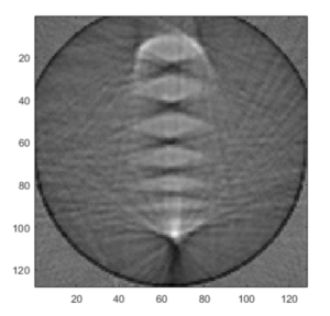
Using the template for image reconstruction in Matlab, we were able to input our data collected for voltage, stepper angle, and servo angle along with some physical constraints of our system and desired output image. We had to convert our single detector voltages into fan beam data in order to reconstruct the sinograms from our voltages. From here, we simply used the radon function in Matlab to convert our sinograms to an image. The reconstructed image still has some slight parameter changes necessary to optimize the image, however the output image looks like our phantom! We will continue to alter the fan center angle and width to increase resolution, and test our system on other phantoms in the upcoming week.
Image 1: Code for the Matlab reconstruction (using template)
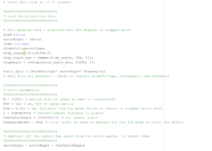
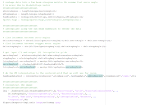
Image 2: The reconstructed image of the phantom
Questions
- Image Errors
- Question: Do all the features in your phantom images have the correct size? If not, why? Are their sizes accurately represented in all dimensions?
- No, not all the features in the phantom image have the correct size. Our phantom image is much more rounded than the rectangular extrusions of our phantom. The overall size and spacing of our phantom image reflect our actual phantom, but the fine details (especially corners) are distorted.
- Question: Do all the features in your phantom images have the correct size? If not, why? Are their sizes accurately represented in all dimensions?
- Artifacts and Resolution
- Question: What happens if you more coarsely or finely sample the fan beam angle and/or stepper motor positions?
- Currently, the stepper motor has a step angle of 1.8 degrees and our servo has a step angle of 1 degree for each measurement taken. This makes our stepper motor the limiting factor with spatial resolution. We think that by more finely sampling the servo, we would see no change in image resolution because the servo is not the current limiting factor. However, by more finely sampling the stepper motor, we would be able to increase the spatial resolution of our image and perhaps better image the finer details of our phantom.
- Question: What happens if you more coarsely or finely sample the fan beam angle and/or stepper motor positions?