Morgan Kinney, Tanner Hoppman, Jude Franklin
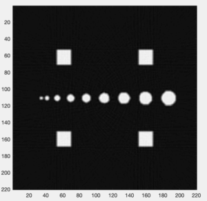
This week we spent much of our time troubleshooting an issue with an unknown cause, which we finally resolved with the discovery that our IR LED no longer functioned. This issue was seen in the fact that our serial monitor did not output changing values as the the distance between our LED and diode was varied. Once confirming that our emitter-detector system was working and being measured properly, we programmed the arduino to print to the serial monitor the three values we will need for reconstruction: voltage measurement, servo angle, and stepper angle. We were also able to finish our reconstruction program in matlab and test it on sample projection data to obtain an image (Fig. 1-2). The last steps to being able to reconstruct to an image will be modifying the scan parameters for the servo and stepper motors to get the best image and transferring the data into Matlab.
Figure 1. MATLAB code for fan-beam reconstruction of sample projection data
clear all
load fanBeamProjectionData
theta1=reshape(stepperAngle,269,360);
voltage1=reshape(voltage,269,360);
[rad, xp]=radon(voltage1,theta1(1,:));
figure(1)
imagesc(theta1(1,:),xp,voltage1)
colormap(hot)
colorbar
N = 220; % matrix size
FOV = 10; % cm, FOV of image matrix
Dcm = 7.78; % cm, distance from fan beam vertex to center of stepper motor shaft
D = Dcm*N/FOV; % vertex->center distance in pixels
figure(2)
img = ifanbeam(voltage1,D,’FanSensorSpacing’,.5,’OutputSize’,N);
imagesc(img);axis image;colormap gray
Figure 2. Reconstructed image from sample projection data

Question: Which way does your photodiode need to be oriented to get a positive output voltage?
Answer: The photodiode needs to be oriented with the positive end connected to ground and the negative end connected to the inverting input of the op amp. This allows for the negative current through the photodiode to be powered by the op amp from the output to ground.
