
Jorie Budzikowski, Stephanie Molitor, and Rachel Welscott
This week we were able to work on:
- Imaging various phantoms
- Changing image collection parameters including step size, light around the detector, field of view, etc.
1. Imaging Various Phantoms
Last week we were able to complete our servo, stepper motor, and Arduino code. We also were able to complete the image reconstruction of our first phantom. This week we aimed to continue to gather data with different phantoms and altered parameters on the image reconstruction script including the field of view, fan angle width, and distance from the center of the phantom to the servo motor to get a clear image. Some of the relevant image parameters we aimed to investigate were the image resolution, the smallest detectable line pair, image artifacts, and image scale size. The actual code changes for this week are minimal, but the changes to the sinogram and the corresponding phantom image were significant.
We were able to make reconstructions of three different phantoms, shown below. The overall quality of these reconstructions is decent, as we were able to discern the general shapes and spacing. However, some distortions were present, such as blurring of edges that turned square shapes more round. Additionally, we found the second phantom (middle image below) produced the least clear reconstruction. We found that this was due to the outer four pegs blocking the IR light from the inner pegs. Since our CT scanner only took images in one direction at a time, this altered our final reconstructed image.

Image 1: The three different phantoms we were able to produce images of using our Infrared CT scanner system.
2. Changing Image Collection Parameters
We also changed the step size for both the servo and the stepper motor to determine how the step size correlated to image resolution. We changed the servo step size from 1 to 5 degrees, and changed the stepper motor from 1.8 to 3.6 degrees. We were able to change the step size very easily, by only changing one value in our Arduino code, as shown below. We determined that an increased step size for both the servo and of the stepper motor resulted in a decreased image resolution, as illustrated in the following image reconstructions.

Image 2: Increasing the servo step size (left) and increasing the stepper motor step size (right), both had the effect of decreasing image resolution.
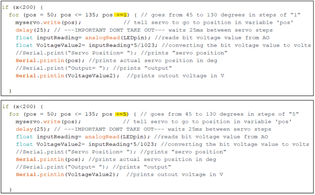
Image 3: The Arduino code, showing the parameter changes to alter the step size of the servo from a step size of 1 (top) to a step size of 5 degrees (bottom).
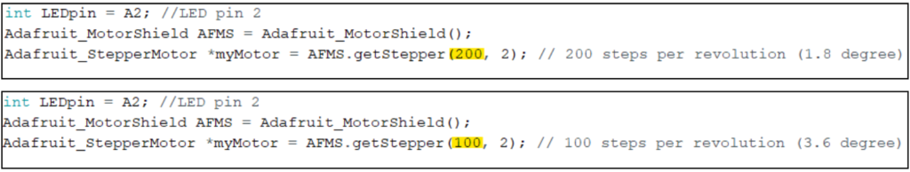
Image 4: The Arduino code, showing the parameter changes to alter the step size of the stepper motor from a step size of 1.8 (top) to a step size of 3.6 degrees (bottom).
The next parameter we changed was the lighting around our detector. We were working by the window, so we found that the generated sinogram showed different colors on the window side and classroom side of the image. This would impact the resolution of our image reconstructions by changing the grayscale coloring of the phantom. By covering our CT scanner with jackets to block the light during the collection, we were able to eliminate this variability in coloring of the image due to the lighting and produce a more consistent ambient environment signal.
Additionally, one of the artifacts that we noticed in our reconstruction was a dark ring around the outside of each phantom (see Image 1). We believe that this was due to a high level of noise at the upper end of our fan angle. This is easily seen by the blue stripe on the far right of our sinograms. By cropping the fan angle in our reconstruction to only capture the bulk of the sinogram, we were able to make this dark ring less apparent.

Image 5: Two sinograms produced from an unlit (left) environment and an environment with ambient light (right). Both sinograms feature a dark blue stripe on the far right, which is what produced the dark ring around our image reconstructions.
The questions that we aimed to answer in this lab are as follows:
- What is the smallest feature or line pair that you can resolve?
- The smallest gap between phantom pegs that we were able to resolve in our image reconstruction was measured to be 0.445 inches.
- What happens if you more coarsely or finely sample the fan beam angle and/or stepper motor positions?
- Last week, we hypothesized that a smaller step size for the servo and stepper motor would produce finer spatial resolution. This week, we were able to test our hypothesis and found that we were correct, as increasing the step size of each resulted in a very poor image reconstruction.