Week 6
Javier and Nicholas J. Holden
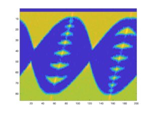
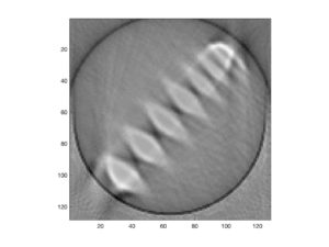
Sadly, this is our last week looking and working with our homemade CT machine before we decided it needed to be destroyed. We ran our last data collection on several different phantoms for the report. We felt accomplished because we had tangible results. We tried to fully reconstruct the image but ran into some problems because the resulting image looked nothing like our phantom. After speaking with the Professor, we realized that we had incorrectly measured our dcm. Our previous thought was that it was the distance from the middle to the photodiode; however, it is the distance from the middle to the servo motor. We also played around with our servo center angle to try and correctly align our sinogram to the middle. Figure 1 demonstrates the finished sinogram. Notice how it is nicely aligned in the middle of the window. Figure 2 illustrates the reconstructed image of the phantom.
We also began our ultrasound lab. Our mold that was created last week turned out fantastic. The ice bath contributed to the success because of the lower temperature we were able to achieve before we stopped stirring. We also began to solder pieces to our electric board. I cannot begin to describe the frustration that Javier and I (Nicholas J. Holden) experienced when trying to solder the inductor to the board as it was a small and easily breakable component. Eventually, we were able to correctly solder it and were able to finish the TR switch. We still need to test the switch to ensure the TR switch is functioning like expected.
Question: What values do you get for L and C?
Answer: 1.59μH for the inductor and 636.5pF for the capacitor
Question: How close can you get to these values with the components we have (without, e.g. using multiple components in each position)?
Answer: We were able to get 1.5μH inductor and a 680pF capacitor.
Figure 1 – The sinogram

Figure 2 – Reconstructed image of our phantom

