
This week, we built our T/R switch and measured power return loss. After calibrating, we measured the power return loss at each port. We got a higher power return loss than expected, so we realized that we accidentally used 6.8 pF capacitors instead of 680 pF capacitors. Then, we used 680 pF through-hole capacitors. Dr. Grissom warned us that he did not know how these capacitors would react to radio frequency, so we replaced these capacitors with the surface mounted ones we were given. Below are the power return losses we observed from each port with the different capacitors.
Through-hole capacitor
Transmit out port
Receive open: 1.32 dB
Receive 50 ohms: 23.05 dB
Receive port
Transmit open: 1.36 ohms
Transmit 50 ohms: 9.46 dB
Surface mounted capacitor
Transmit in port:
Transmit out is open: 0 dB
Transmit out 50 ohms: 0 dB
Transmit out port:
Receive open: 0.77 dB
Receive 50 ohms: 23.57 dB.
Receive port:
Transmit out open. 0.77 dB
Transmit out 50 ohms. 23.31 dB
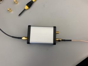
Figure 1: T/R switch set to 5 MHz input to transmit out looking at receive port
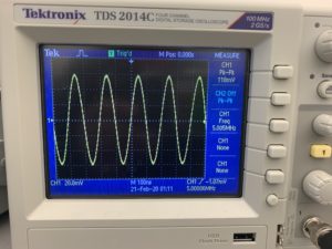
Figure 2: Oscilloscope of T/R switch set to 5 MHz input to transmit out looking at receive port
Question:
With the components we have, how close do you come to satisfying the two conditions above?
We used a 680 pF capacitor and and a 1.5 uH inductor. The capacitor is slightly larger and the inductor is slightly smaller than the desired values.