
Week 7
Javier and Nicholas J. Holden
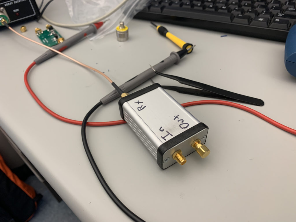
This week was spent on trying to make sure that the TR switch was constructed and functioning properly. Figure 1 shows the soldered circuit. Upon testing the circuit for the first time, we discovered that the inductor was not properly soldered onto the board. This in turn created a break in circuit at the inductor. This was incredibly frustrating because they were difficult to replace due to being delicate. After solving this problem, we then tested that the circuit was continuous. Once this was confirmed we resumed testing for return loss. We encountered a problem when we first did the testing, but we discovered that the error wasn’t from the TR switch but rather the antenna analyzer. This was discovered by testing a working TR switch and observing a very low return loss for Tx-Out with a 50 Ohm load on the Rx port. Figure 2 displays the outer shell of the circuit that was attached with the ports labelled. Upon switching out the analyzer, the return loss was then collected for a variety of situations. This includes a -9.14 dB return signal with the analyzer connected to Tx-Out and a 50 Ohm load on the Rx port. The reverse of this situation was also tested and returned -9.27 dB. This was good as it should be symmetric. When the 50 Ohm load is removed, the return loss in both situations are 0.64 and 0.62 dB. Finally the Tx-In port was tested and had a return loss of .02 dB which is what we expected to occur. Next week, we will get started on running the GNURadio and SDR in order to create a pulse signal as well as familiarizing ourselves with the GNURadio.
Figure 1
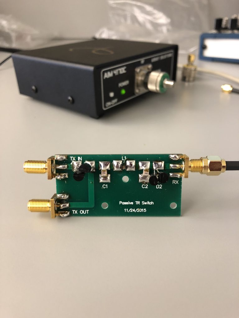
Figure 2
Question: How would you express this mathematically?
Answer: You would express this as an infinite amount of impedance preventing the flow of current. This makes the circuit appear as an open circuit.