
Morgan Kinney, Tanner Hoppman, Jude Franklin
This week while finishing our data acquisition for the IR CT scanner we were able to begin working on our next project, the ultrasound machine. Our first step was creating the phantom to be imaged once we build our ultrasound probe. This was done by combining water with agar and graphite, heating it up in a microwave, and then cooling it and inserting a 3-D printed shape part-way through the cooling process. Next, we built our transmit/receive switch using the board shown in Fig. 1 to match the circuit diagram in Fig. 2 with ceramic chip capacitors, a surface mount inductor, SMA connectors, and four Schottky diodes. The last thing we did was enclose our switch in a metal enclosure for storage so that our next step will be to test it to make sure our soldering has been done properly.
Figure 1. Transmit/Receive switch board used to build T/R switch.
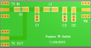
Figure 2. Transmit/Receive switch diagram. The quarter-wave line is modeled through a pi network of two identical capacitors and an inductor.
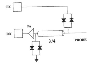
Question: Under what conditions do each pair of crossed diodes turn on?
Answer: In Fig. 2, the diodes between TX and the probe turn on when the TX amplifier produces large voltages during transmit to induce a loss of power, and the other diodes turn on when the transducer acts as a source producing small voltage signals during receive.