Ultrasound Update 2: March 17, 2020

Morgan Kinney, Tanner Hoppman, Jude Franklin

This week we were able to complete the building and testing of our T/R switch. Since we were unsure the cause of our T/R switch malfunctions from before, we re-soldered all of the components, which fixed the issue. The return loss measurements at each port shown in Element 1 were all within expected ranges, indicating our switch was working properly. The image in Element 2 was obtained by injecting a 5 MHz signal into the transducer port and measuring the signal at the receive port. The signal remaining at 5 MHz frequency also indicates that our switch was functioning properly.


Element 1. Return loss measurements at each port of the T/R switch.

tablereturnloss

Element 2. Image of oscilloscope measuring the 5 MHz signal detected at the receive port of the T/R switch when a 5 MHz signal is generated through the transducer port.

osimage

Question: How would you express this (an open circuit) mathematically?

Answer: An open circuit is represented mathematically by an infinite impedance, so that there can be no current flow.

3/10/2020: Ultrasound Scanner Update #2

This week, we began making a sinusoidal function generator to test our T/R switch. Below is the pulse-echo sequence flow graph we made that outputs a pulse of 1 microsecond duration separated by a tunable pulse repetition time.

1

Figure 1: Block diagram of our multiplier

Question: The simplest solution using the above three elements has an upper limit on the pulse repetition time because of the very large delays required. How can you modify it so you only use a 1 microsecond delay?

By inverting any given time varying signal (i.e. multiplying by -1 so as to flip all the values about the time axis) and then summing the inverted and non-inverted signals together, the result will be 0. Using this approach to generate the 1 microsecond delay is more feasible since it does not require a large amount of memory bandwidth. Given a 1 Megahertz signal, the period for a single sample will be 1 microsecond. By delaying an inverted 1 MHz signal one sample we are in essence generating two signals (one inverted one non-inverted) that differ by only 1 microsecond. By summing these two signals together, we generate a pulse of only 1 microsecond. Our block diagram is shown in Figure 1.

Below are images of the progress we made on the ultrasound scanner before Vanderbilt yeeted us out.

2

Figure 2: Sinusoidal source waveform

3

Figure 3: Pulse width modulation signal. This scope capture represents our efforts at attempting to generate the 1 microsecond pulse

4

Figure 4: This picture shown above represents our first attempt at generating the 1 microsecond pulse delay. This approach fails since it requires us to delay the second signal by too many samples which requires too much memory bandwidth.

5

Figure 5: This waveform shown above represents the 1 microsecond pulse that we successfully generated using the radio blocks in Fig.


Ultrasound Scanner: Week 3 Blog Post

Myron Mageswaran, Alex Boyd, and Maggie Ford


During week 3 for this lab, we first tinkered with the GNURadio software in order to create the desired input into the switch using the radio shown in Figure 1.  This task took longer than expected, but we were able to set up an input signal that was pulsed for one microsecond using the schematic shown in Figure 2.

Screen Shot 2020-03-16 at 10.46.10 PM

Figure 1:  the software defined radio that is interfaced with the Linux virtual machine

Screen Shot 2020-03-16 at 10.47.00 PM

Figure 2: block diagram schematic

After programming the Arduino, we were ready to take our first scan and took out our cast out of the mold and filled our bin with water only to realize that we only had three minutes remaining in class, (and unsuspectingly the rest of the semester) so we did not have time to take any actual readings.

Question: What is the purpose of the quarter wave line?                                                  The quarter wave line is able to change impedance creating either an open or closed circuit to Rx, which creates the switching effect.

Blog Post Week #3: Imaging Instrumentation Ultrasound Lab

Blog Post Week #3: Imaging Instrumentation Ultrasound Lab
Jorie Budzikowski, Stephanie Molitor, and Rachel Welscott

This week we worked on:
I. Making a pulse-echo sequence
II. Programming the Servo to sweep through a range of angles for B-mode imaging
III. Finalized our setup prior to data acquisition

I. Making a pulse-echo sequence
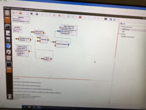
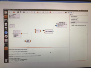
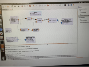
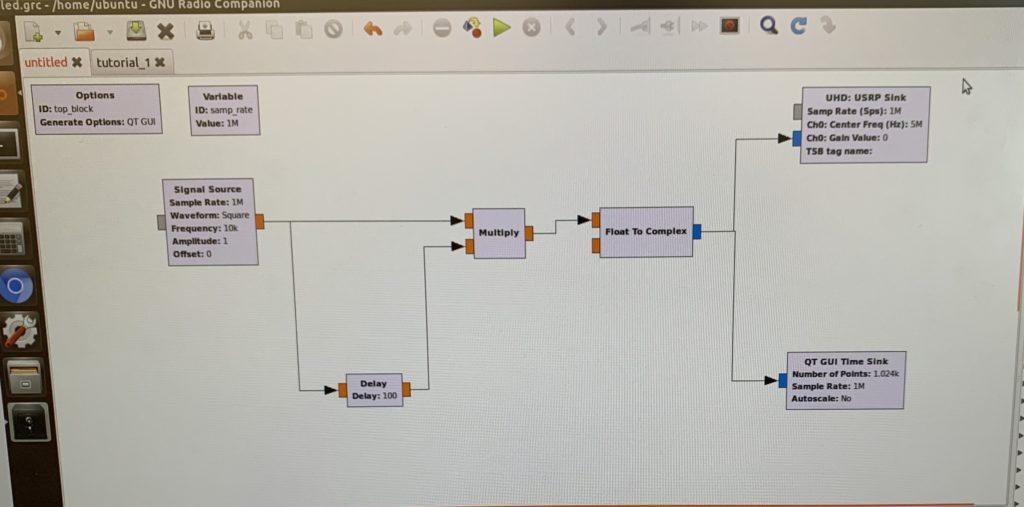
Once we got a basic sinusoidal function generator functioning through the GNU Radio software (Figure 1), we were able to alter the conditions of the signal source to create pulses that are 1 microsecond in duration. We are able to do so by introducing a delay, a multiplier, and an additional function to our square wave source. The pulse is sent to the radio, will be amplified, and then transmitted through the ultrasound probe. We also added a radio source and GUI sink component in order to read what signal is reflected back from the ultrasound transducer. The block diagram for our pulse-echo sequence is shown in Figure 2.

5 mhz
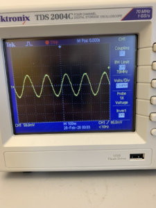
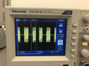
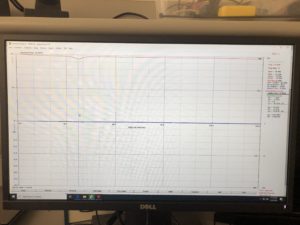
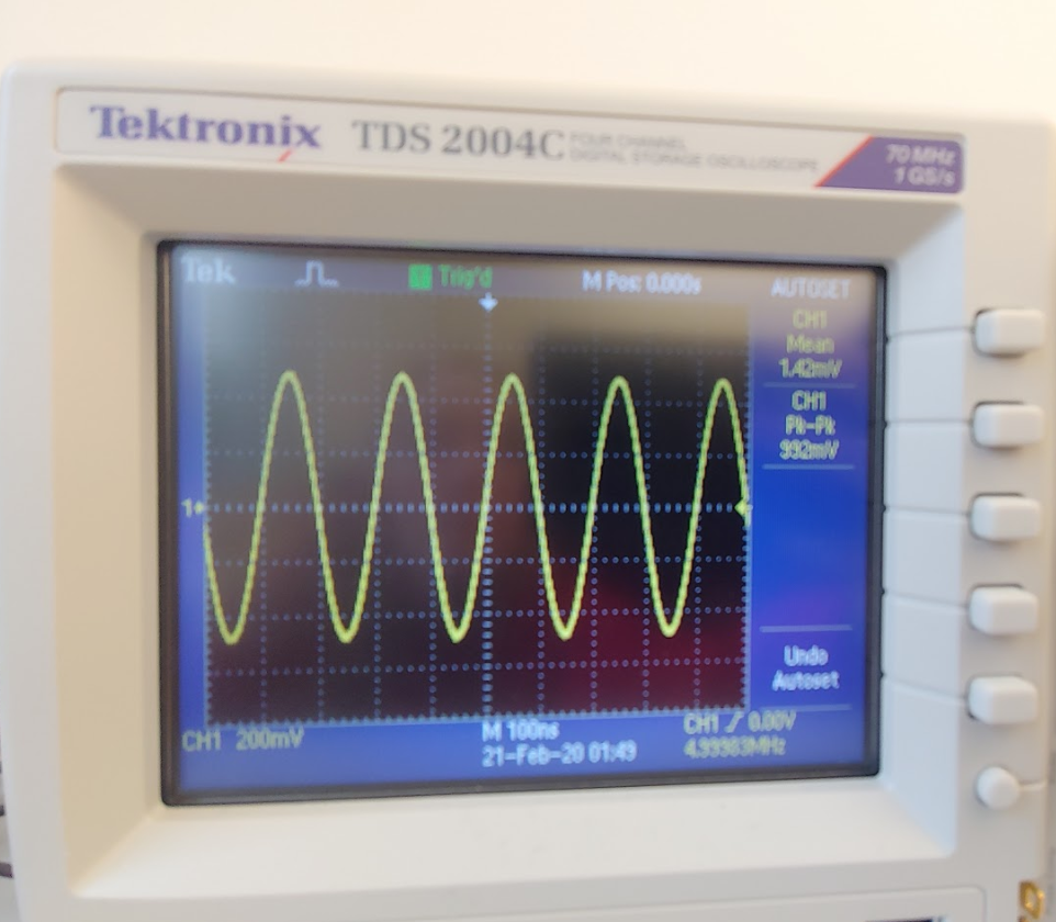
Figure 1. Simple 5 MHz sinusoidal signal from our function generator using the USRP radio.

USRP
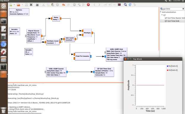
Figure 2. Block diagram for our pulse-echo sequence.

pulse
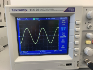
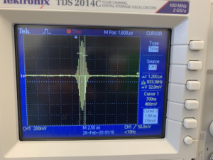
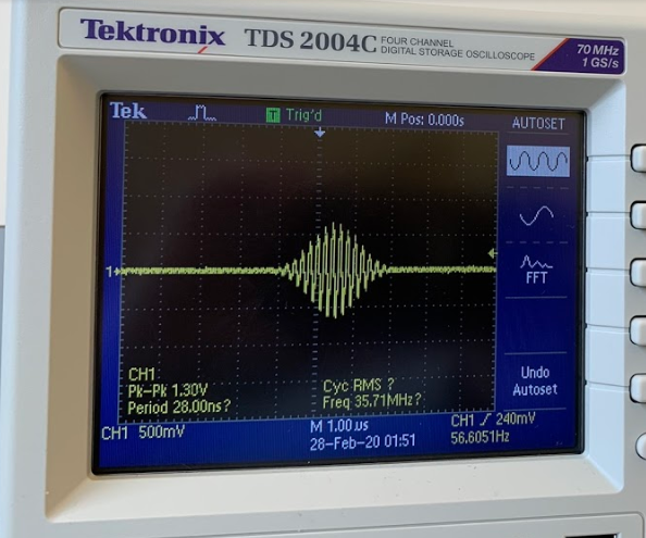
Figure 3. Oscilloscope readout of our 1 us pulse signal from the URSP radio.

II. Programming the Servo to sweep through a range of angles for B-mode imaging
The arduino was programmed to move to the angle plugged into the serial monitor. The servo object was first created and the serial monitor was initialized. The position variable (pos) was initialized and set equal to the read in value that was entered into the serial monitor. Next we used an if statement to ensure that the value that was inputted into the serial monitor is attainable by the servo motor. Finally, the inputted position was written to the servo motor so that ultrasound probe was pointed at the intended angle. See the attached video of our servo moving the ultrasound transducer.

servo
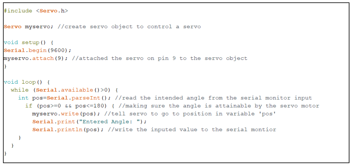
Figure 4. Arduino code to control the servo arm and have it move to a desired angle.

III. Final Equipment Setup Prior to Data Acquisition
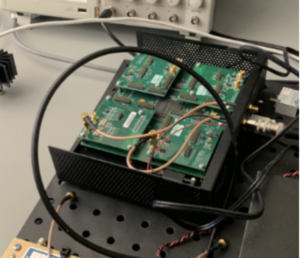
Now that we have programmed our URSP radio to transmit and receive signals, and programmed our servo arm to move the transducer, we are ready to start collecting some ultrasound data!

setup
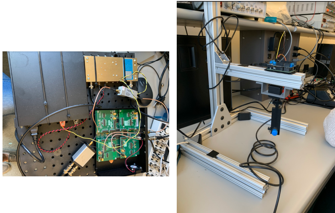
Figure 5-6. The electronics of the ultrasound probe system and the physical probe-stand tabletop model.

Questions to answer this week:

  • Question: How can you do this using a single square wave signal source, a delay, and a signal multiply block?
    • You can send the single pulse as an input into two different operator functions. One of the functions should not do anything to the waveform while the other function adds a delay and a multiplication constant. These 2 new wave forms are then multiplied together to result in a square waveform with a very short pulse width.
  • Question: The simplest solution using the above three elements has an upper limit on the pulse repetition time, because of the very large delays required. How can you modify it so that you can use only a 1 us delay?
    • The simplest solution only involves the signal source, a delay, and a multiplier. We originally planned to use a large delay with this setup; however, due to the upper limit we found that we had to modify our design. We instead changed the used a short delay in combination with an addition operation to get a 1 us delay.

CT Scanner Week #8 – 2/28/2020

Week 8

Javier and Nicholas J. Holden

This week was spent working with the radio in order to try and get the radio to release a pulse for the ultrasound. The beginning of the week was primarily about getting used to the GNUradio by doing the different tutorials given by the software and viewing the results using the oscilloscope. Once these were finished, we attempted to create the pulse wave needed for the ultrasound. We figured out the parts needed in order to create the wave. We did encounter some issues in this process primarily because of getting the pulse duration just right by deciding the timings of the different pieces and amounts.  


Nicholas J. Holden persevered on Thursday due to teammate and hardware specialist, Javier, having to attend to a sensitive matter. The beginnings of the Arduino code was formed in an effort to begin work to move the ultrasound sensor around the artifact. Unfortunately, this did not get too far in the development stage. Nicholas J. Holden then tried to work on the GNUradio with the software associated with the device. Little progress was made, however, much was learned from Grissom who gave a short lecture to two groups about the overall direction he wanted groups to go with the software.

Figure 1 – illustrates the sinusoidal wave achieved with the radio.

IMG_1291 copy

Figure 2 – illustrates the software we have working with to generate the appropriate waves.

IMG_1305 copy

We are currently trying to survive the Coronavirus and will continue to update this blog and the continuation of our work.

Question: What is the role of the quarter-wave line?

This allows the path to the Rx port to seem like an open or closed circuit by changing the impedance of the line. This wire has to be a quarter of the length of the wavelength of the wave being used.


Week 8: Ultrasound Scanner (Coronavirus edition!!!)

Week 8 Blog Post: Ultrasound Scanner

Hunter Spivey and Aayush Gupta

This week we began to test the T/R switch using our antenna analyzer but were running into issues with return loss measurements. Our return loss measurements were for the most part as expected, with us getting a return loss of zero when sending signal into the TX in port. However, our return loss when sending signal into the RX port was only about 3 dB whereas we had been expecting about 10 dB. We attempted to solder the components onto the board better, but this made little difference and we were still only getting about 6 dB. After struggling with this, replacing our inductor, and still getting only 6 dB, we recalibrated our antenna analyzer program and were finally able to get the 10 dB return loss we expected. Now with confirmation that our T/R switch was indeed working as we expected, we moved on and began setting up our GNU radio software. Unfortunately we ran out of time before we could get very far with our software though, and were only able to get it started and run through some basic tutorials.

We next hope to finish the GNU radio software provided coronavirus doesn’t do us all in/we even have class anymore?

Return Loss of TX in:

IMG_3124

Question: How close can you get to these values (L and C) with the components we have (without, e.g. using multiple components in each position)?

Answer: We can use a 1.5 microHenri inductor and two 680 picoFarad capacitors