
This week, we began making a sinusoidal function generator to test our T/R switch. Below is the pulse-echo sequence flow graph we made that outputs a pulse of 1 microsecond duration separated by a tunable pulse repetition time.
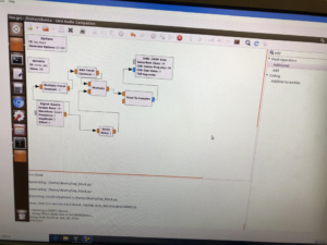
Figure 1: Block diagram of our multiplier
Question: The simplest solution using the above three elements has an upper limit on the pulse repetition time because of the very large delays required. How can you modify it so you only use a 1 microsecond delay?
By inverting any given time varying signal (i.e. multiplying by -1 so as to flip all the values about the time axis) and then summing the inverted and non-inverted signals together, the result will be 0. Using this approach to generate the 1 microsecond delay is more feasible since it does not require a large amount of memory bandwidth. Given a 1 Megahertz signal, the period for a single sample will be 1 microsecond. By delaying an inverted 1 MHz signal one sample we are in essence generating two signals (one inverted one non-inverted) that differ by only 1 microsecond. By summing these two signals together, we generate a pulse of only 1 microsecond. Our block diagram is shown in Figure 1.
Below are images of the progress we made on the ultrasound scanner before Vanderbilt yeeted us out.
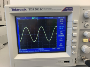
Figure 2: Sinusoidal source waveform
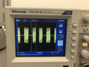
Figure 3: Pulse width modulation signal. This scope capture represents our efforts at attempting to generate the 1 microsecond pulse
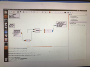
Figure 4: This picture shown above represents our first attempt at generating the 1 microsecond pulse delay. This approach fails since it requires us to delay the second signal by too many samples which requires too much memory bandwidth.
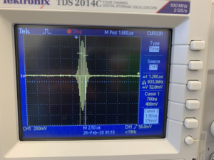
Figure 5: This waveform shown above represents the 1 microsecond pulse that we successfully generated using the radio blocks in Fig.