
Morgan Kinney, Tanner Hoppman, Jude Franklin
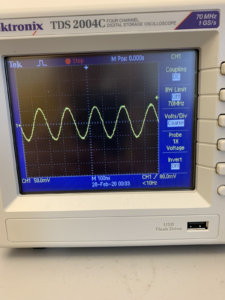
This week we were able to complete the building and testing of our T/R switch. Since we were unsure the cause of our T/R switch malfunctions from before, we re-soldered all of the components, which fixed the issue. The return loss measurements at each port shown in Element 1 were all within expected ranges, indicating our switch was working properly. The image in Element 2 was obtained by injecting a 5 MHz signal into the transducer port and measuring the signal at the receive port. The signal remaining at 5 MHz frequency also indicates that our switch was functioning properly.
Element 1. Return loss measurements at each port of the T/R switch.

Element 2. Image of oscilloscope measuring the 5 MHz signal detected at the receive port of the T/R switch when a 5 MHz signal is generated through the transducer port.
Question: How would you express this (an open circuit) mathematically?
Answer: An open circuit is represented mathematically by an infinite impedance, so that there can be no current flow.