
Blog Post Week #2: Imaging Instrumentation Infrared CT Lab
Jorie Budzikowski, Stephanie Molitor, and Rachel Welscott
(overheard) QUOTE OF THE WEEK:
“You know I am just really skeptical because Dr. Grissom DID NOT say to do that.”
This week we made significant progress on our CT scanner. We completed the circuit elements of our CT scanner including the IR LED and the photodiode circuits shown in Image 1 below. Using a multimeter, were able to verify that our circuit was working correctly such that the output voltage decreased when the path between the IR emitter and the photodiode was blocked. We tuned our feedback resistor value to get readout voltages in the desired range (2-3 V with full IR exposure). We then were able to program our Arduino to report the proper output voltage value on the serial monitor. A video of this Arduino readout is shown in the first video below.
Image One: The complete IR LED and photodiode circuits attached to the Arduino Uno that provides the power to the circuits.
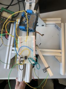
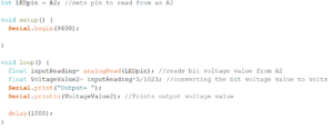
Image Two: The Arduino code that prints the output voltage from the above circuit.
Video One: The display of output voltage from the photodiode is shown on the serial monitor of the Arduino. When the photodiode is uncovered, the voltage is around 3 V. When the photodiode is covered, the voltage values are around 0V.
Questions we set out to answer this week:
- Question: What does the datasheet say to do with the unused amp on your chip? Does doing this affect your images in any way?
- The unused amp pins are all connected to ground. This has allowed a current to voltage conversion in our circuit, but we have yet to actually collect any images.
- Question: What does the datasheet say about the maximum voltage you can get out of the op amp? What is the max voltage you actually get?
- The datasheet says that the maximum rail (V_DD) voltage that op amp can handle is 5V. This implies that the maximum voltage that you can get out of the op amp is 5V. However, the datasheet also lists the minimum and typical high-level output voltages for the op amp as 3.2 V and 3.8 V, respectively. The datasheet does not list the maximum high-level output voltage.
- The max voltage that we were able to measure from the op amp was 3.6 V.
- Question: Can you optimize the value of the feedback resistor to use as much of the Arduino’s input range as possible, between light and dark states, when the LED and photodiode are set 10 cm apart in their holders?
- We were able to optimize the value of the feedback resistor by choosing a 4.7 megaOhm resistor. This allowed us to reach approximately 3.5 V maximum when the LED was uncovered and 0 V minimum when the LED was covered.