
Hunter Spivey and Aayush Gupta:
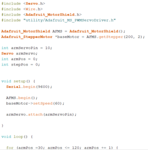
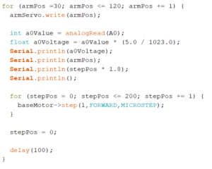
This week be managed to connect our stepper motor to our adafruit motorshield via the M1 and M2 ports and run it via our arduino code. We initially had connected it via the digital pins, but eventually rewired it. Following this we began to work on reading our output from out current-to-voltage converting circuit into our arduino’s analog input, and displaying it on arduino’s built in serial monitor. We were able to successfully do this, and we confirmed that the displayed values would change if we blocked the incident IR light on the photodiode. After this we then moved on to connecting our fan arm servo to the arduino board, and writing the code to move it in the correct direction. We initially struggled to connect the servo properly, but after working with it for a bit, were able to connect it and write the code to move it over a specified angle. Finally we worked on cleaning up our wire connections to make it a little bit tidier and less all over the place.
Our next goal is to work on interfacing the arduino serial monitor output with Matlab so we can use the measured voltage values to try and reconstruct an image of the phantom.
Video:
Below is a video of where our scanner was at when we finished by the end of last week. We have changed the code so that the stepper motor only takes one step per sweep of the fan arm, although this video does not reflect this change.
Code:
Additionally, we have modified the code to be cleaner, as well as to address the change in the stepper motor previously described. Images of the new code can be found below.
Question:
The servo has an extra (white) wire on it, that reads out its built-in position potentiometer, which you can use to record the servo’s actual position (rather than just its intended position). Is your image reconstruction improved by using this value instead of the intended value?
Answer:
Because this would give us the actual position of the fan arm as opposed to what we told it it should be at, then yes, using the white feedback wire could potentially improve the accuracy of our servo’s position recording. However, since we are not moving the fan arm at a very high rotational speed, the use of this more accurate feedback wire isn’t necessary as our servo should have more than enough time to reach the position we instruct it to. If the servo as a whole is off on its positioning, then it could become an issue, but for our current purposes it isn’t required.