
Blog Post Week #5
Aayush Gupta & Hunter Spivey
This week we were finally able to reconstruct the data obtained from the Arduino and obtain a reconstructed image from the stepper and servo data of our CT scan. The MATLAB code used to parse the data and produce an image is displayed below, with appropriate comments included:
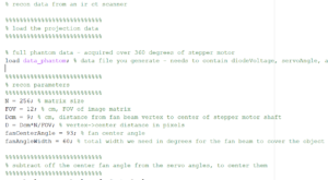
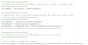
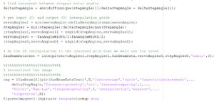
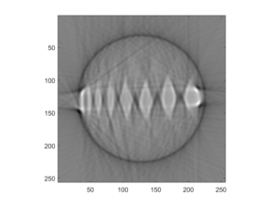
A problem we faced while trying to produce our reconstructed image was that initially we set our stepper motor to record 201 voltage values per revolution instead of 200, which led to a sinogram that was tilted. After we realized our error, we modified our code and got the image below for our phantom:
The question that we sought to answer this week were:
Q: Do all the features in your phantom images have the correct size? If not, why? Are their sizes accurately represented in all dimensions?
A: No they do not, our reconstructed image is a phantom that is significantly less geometric than our original phantom- our original’s dips and crevices were much straighter than shown in the reconstructed image. However, for the most part they resemble one another, with the only difference being that the image was not as detailed and did not include many of the more difficult detail
Hopefully next week we can quantify image errors discretely and discern to what extent our reconstruction correlates to the original phantom.