
Blog Post Week #1: Imaging Instrumentation Ultrasound Lab
Jorie Budzikowski, Stephanie Molitor, and Rachel Welscott
(overheard) Quote of the Week:
“Careful, they will draw blood.”
This week we worked on:
I. Making the phantom
II. Soldering the T/R switch
III. Calibrating the AIM Antenna to 50 Ohms
I. Making the Phantom
This week, we were able to prepare a phantom that will be used later in testing. We combined agar, graphite, and water and microwaved the mixture until it was just barely boiling. This allowed all of the ingredients to mix together homogeneously. We stirred the mixture continuously until it cooled to 40 degrees C in order to prevent premature separation of the mixture. As it cooled the rest of the way, we inserted a 3D printed phantom into the beaker, which will be what we ultimately want to image. The graphite and agar surrounding the phantom simply allow the light to be reflected so we receive a realistic signal.
II. Soldering the T/R Switch
The T/R switch consisted of a PCB along with components including two capacitors, two sets of two diodes, and an inductor. Each component was soldered onto the PCB according to the figure below.

Figure 1. Circuit diagram of T/R switch.

Figure 2. Soldered PCB for T/R switch, based off of the above circuit diagram.
The component values for the inductor and capacitor were derived using the desired frequency and impedance values according to the L and C equations below. Using a frequency of 5 MHz, we were able to determine that the ideal capacitance value was 1.6 microHenrys and the ideal inductance value was 636.6 picoFarads.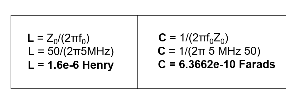
Equations 1-2. Derivations for inductor (L) and capacitor (C) values used in the T/R switch using a frequency of 5 MHz.
Once it was soldered, the PCB was housed in a steel box (Figure 3) to protect us against the high voltages that will be produced during transmission.
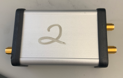
Figure 3. Steel housing that encases the T/R switch during data collection.
III. Calibrating the AIM Antenna to 50 Ohms
The purpose of the AIM Antenna is to send a signal to the transducer and receive the reflected signal back. This measures the return loss, which is the amount of power that is reflected back from the switch at each of the ports of the constructed T/R switch. The AIM Antenna was calibrated using the AIM_916 software on the PC. Following the standard calibration procedure within the program, the antenna was calibrated first using a short circuit, then an open circuit, and finally 50 Ohms to match the impedance of the cables. This calibration was saved and will be used for data collection in the coming weeks.
Questions we aimed to answer this week
- What values do you get for L and C?
- L=1.6 microHenrys
- C= 6.3662e-10 Farads
- How close can you get to these values with the components we have (without, e.g. using multiple components in each position)?
- The actual values we used were limited by those available in the inductor and capacitor kits. We ended up using values of L=1.5 microHenrys and C=680 picoFarads.