
Jorie Budzikowski, Stephanie Molitor, and Rachel Welscott
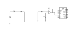
This week we designed a two circuits, one to power the Infrared LED and the second to amplify the signal received by the photodiode. We also began to test the signal from the IR to the photodiode and physically implemented both of these circuits onto the servo itself. Our designed circuit consists of two parts, the first of which is an infrared LED circuit. The IR LED is powered by a 5 V supplied by the Arduino Uno. A resistor separates the LED from the power supply to ensure that too much voltage is not applied across the LED damaging it. The second half of the circuit is a current-to-voltage converter. The photodiode receives light emitted from the IR LED, which results in a current output from the photodiode. This current is directed into the positive terminal of the op amp. The noninverting op amp has a feedback resistor that amplifies this input and results in an output voltage proportional to the current supplied by the photodiode. This essentially converts the IR from the LED to voltage that can be recorded by the Arduino.
The circuit design on our breadboard and Arduino is as shown in the schematic below:
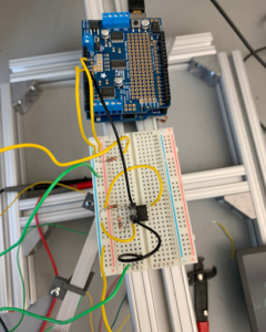
The circuit diagram implemented onto the breadboard and the Arduino:
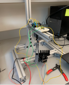
Finally, the entire servo, circuit, Arduino, and phantom together:
Next week, we will continue to finalize the circuit design and program the Arduino to communicate with the servo.