Morgan Kinney, Tanner Hoppman, Jude Franklin
This week we were able to obtain our photodiode and infrared LED and secure them into their holders. We soldered lead wires to the ends of each of these to eventually connect them to the Arduino. To power the IR LED, we designed a simple circuit using the Arduino’s 5 volt power source connected in series to the LED and a resistor to decrease the current through the LED and avoid damaging it.
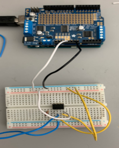
The image below shows our initial attempt at building the photodiode circuit, which is a current-to-voltage converter taking the input current from the photodiode and outputting a voltage through the TLV2322 op amp to be read by the Arduino.
Our next steps will involve optimizing the outputs of both the LED and the photodiode to obtain the best possible data. This will require tweaking of the resistor values in both circuits and evaluating the voltage outputs when the LED and photodiode are at their 10 cm set distance.