Ultrasound Blog 1 (Class Week 6)

Alex Boyd, Myron Mageswaran, Maggie Ford

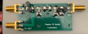
This week the group began prep work for the Ultrasound scanner.  This started by creating a graphite coating on a 3D printed phantom to later be imaged.  The group also soldered elements to a PCB for the T/R switch to be used by the scanner.  Part of the circuit used is displayed below with the switching diodes arrangement shown in the physical PCB picture.  The L and C values for the T/R switch were solved for using these formulas with 5MHz for f0 and 50 Ohms for Z0:   L = Z0/(2πf0), C = 1/(2πf0Z0).  The group also began calibration of the T/R switch for effective measurement of ultrasound waves when the device is complete, but did not complete the calibration steps.

Figure 1. The transmit/receive switch circuit schematic section with inductors and capacitors

T.R switch schematic

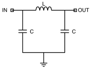
Figure 2. The transmit/receive switch PCB with elements soldered and switching diodes shown.

T.R switch


Question: What values do you get for L and C?

The resulting values were L = 1.59*10^-6 H and C = 636.7 pF which were then rounded to the nearest physical elements available.


IR CT Week 5 Update

This week the group imaged a new phantom and tested changes to the image reconstruction parameters.  Ultimately the tweaking of parameters led the group back to their original inputs as shown in the week 4 blog post.  The baud rate was also adjusted to 14400 to smooth the motion of the servo motor but no improvement was noticed in image quality.  Attached below is the new phantom and resulting image output.  The larger phantom caused issues with resolving the image closer to the edges of the field of view and resulted in blurrier imaging of the posts that in prior phantoms which were smaller and more centrally concentrated.

Fig 1.The new phantom to be imaged

IR CT new phantom real

Fig 2. The resulting IR CT image of the new phantom

IR CT new phantom

Question:

What happens if you more coarsely or finely sample the stepper motor position?

The increase in number of polar steps from moving the stepper more finely results in a higher resolution image with more data points.  If moved more coarsely then the resultant image has fewer data points collected and therefore a lower power to resolve small objects.


IR CT Week 3 Update

Alex Boyd, Myron Mageswaran, Maggie Ford

This week the group refined the cable management and secured the arduino and breadboard to the scanner frame (shown below). The group also increased the fan angle to now sweep 100 degrees in order to image the entire phantom.  The position of the stepper motor and servo are now being read by MATLAB and being placed in individual vectors for interpretation by the image reconstruction script.  Lastly, the image reconstruction script parameters were set by the group.  The students still need to set the inputs to the final image creation function but the initial parameters have been set as seen below.


Input Parameters for Reconstruction

Screenshot (2)

Refined Cable Management

IR CT Scanner

Question: What parameters of your scanner and scan method influence resolution? Investigate these.

  • The size of the servo step between reads influences resolution as well as the distance between the photodiode and IR LED because this changes the focus by changing the scatter angles that are read by the system.

Question: What is the smallest feature or line pair that you can resolve?

  • The actual smallest feature we can resolve will be found (and this answered again next week) when an image is constructed but the resolution will be limited by those factors mentioned in the above question such as servo step size and the size of the focal point of the photodiode.

Infrared CT Scanner Week 1

Alex Boyd, Maggie Ford, Myron Mageswaran

During the first week the group soldered wires to the photodiode and IR LED and constructed the LED driving circuit along with the photodiode circuit to voltage conversion circuit.  The group was able to read voltages using the arduino serial monitor and will now proceed to interfacing the serial monitor with matlab as well as creating code to control the servo motor and stepper motor.

Attached is a picture of the circuit diagram used to construct the current to voltage conversion circuit for input into the arduino.

IR CT Scanner Current to voltage circuit diagram