Week #4
Javier and Nicholas J. Holden
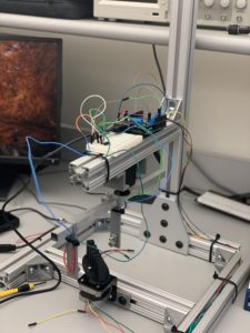
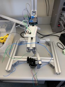
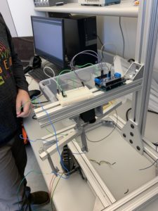
This week consisted of a lot of frustration. Whenever we fixed our servo, the stepper would stop working. When the stepper was fixed, the servo would stop working. We thought there may be a shortage somewhere on the Arduino with a wire touching the board. We also edited the code significantly to see if the issue was code-based and resorted to using the example stepper and servo motor code as a baseline test. The final solution ended up being restarting the Arduino multiple times and crossing our fingers. The solution worked. Upon fixing the system, we rewrote the Arduino code for increased resolution by decreasing both stepper and servo angle to one-degree rotation per sweep and fixing of the rotation of the stepper such that it would rotate fully for each angle of the servo sweep. Once this was done, we then began the process of gathering the data from a full sweep of the CT and importing and saving the data into Matlab.
The next step was to measure and input the different inputs in MATLAB in order to create the reconstructed model of our phantom. The code would be based on the CT recon template provided by Dr. Grissom.
Question: What is the fan angle of your scanner? How many projections will you acquire across this angle, given the resolution with which you can move your servo?
Answer: The fan angle of our scanner was 140 – 55 = 85 degrees. We plan to acquire 17,000 projections. This number was gathered by multiplying the fan angle by the stepper angle. 85 * 200 = 17,000!
It was a short week, but it was filled with a lot of problem solving and adventure. Something that Javier and Nicholas J. Holden aren’t afraid to seek out!
The video below demonstrates the stepper and servo in action collecting data points.
IMG_1047
Below is the code for our Arduino. This update correctly causes our servo and stepper to function. We did two sweeps to increase our Signal-to-Noise ratio.
#include <Servo.h>
#include <Wire.h>
#include “utility/Adafruit_MS_PWMServoDriver.h”
#include <Adafruit_MotorShield.h>
// Setting up pins and angles for the motor
int servopin = 10;
Servo servo;
int angle = 0;
// Create the motor shield object with the default I2C address
Adafruit_MotorShield AFMS = Adafruit_MotorShield();
// Connect a stepper motor with 200 steps per revolution (1.8 degree)
// to motor port #2 (M3 and M4)
Adafruit_StepperMotor *myMotor = AFMS.getStepper(200, 2);
void setup() {
// Opens the serial port
Serial.begin(9600);
AFMS.begin(); // create with the default frequency 1.6KHz
// Sets up setting for the servo and stepper motor
servo.attach(servopin);
myMotor->setSpeed(60); // 10 rpm
}
void loop() {
// Signals to Matlab to begin the collection of data
Serial.println(“Start”);
// Increments through servo angle one at a time
for(angle=55; angle<140; angle+=1){
servo.write(angle);
delay(15);
// Full rotates stepper and gathers data at each stepper angle
for(int step=0; step<200; step+=1){
double sensorvalue = analogRead(A2);
double pot = analogRead(A3);
Serial.print(step);
Serial.print(“,”);
Serial.print(angle);
Serial.print(“,”);
Serial.print(sensorvalue/1023*5);
Serial.print(“,”);
Serial.println(pot/1023*5);
myMotor->step(1, FORWARD, MICROSTEP);
}
}
// Increments through servo angle one at a time
for(angle=140; angle>55; angle-=1){
servo.write(angle);
delay(15);
// Full rotates stepper and gathers data at each stepper angle
for(int step=0; step<200; step+=1){
double sensorvalue = analogRead(A2);
double pot = analogRead(A3);
Serial.print(step);
Serial.print(“,”);
Serial.print(angle);
Serial.print(“,”);
Serial.print(sensorvalue/1023*5);
Serial.print(“,”);
Serial.println(pot/1023*5);
myMotor->step(1, FORWARD, MICROSTEP);
}
}
// Signals to Matlab to end the collection of data
Serial.println(“End”);
delay(10000);
}


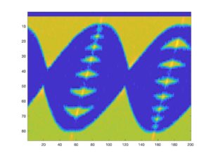
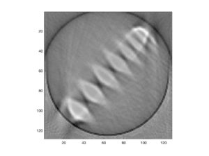
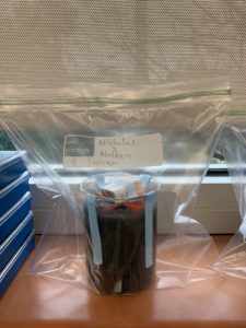
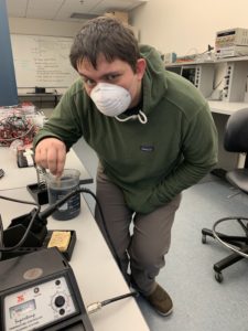 Figure 1 – Javier stirring the graphite/auger mixture