Week 8: Ultrasound Scanner (Coronavirus edition!!!)

Week 8 Blog Post: Ultrasound Scanner

Hunter Spivey and Aayush Gupta

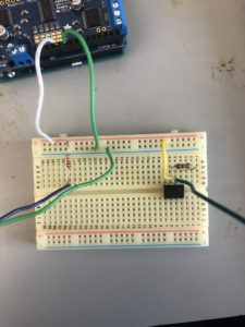
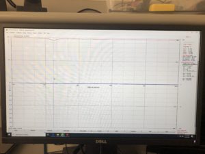
This week we began to test the T/R switch using our antenna analyzer but were running into issues with return loss measurements. Our return loss measurements were for the most part as expected, with us getting a return loss of zero when sending signal into the TX in port. However, our return loss when sending signal into the RX port was only about 3 dB whereas we had been expecting about 10 dB. We attempted to solder the components onto the board better, but this made little difference and we were still only getting about 6 dB. After struggling with this, replacing our inductor, and still getting only 6 dB, we recalibrated our antenna analyzer program and were finally able to get the 10 dB return loss we expected. Now with confirmation that our T/R switch was indeed working as we expected, we moved on and began setting up our GNU radio software. Unfortunately we ran out of time before we could get very far with our software though, and were only able to get it started and run through some basic tutorials.

We next hope to finish the GNU radio software provided coronavirus doesn’t do us all in/we even have class anymore?

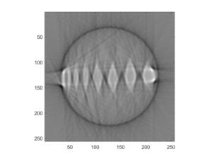
Return Loss of TX in:

IMG_3124

Question: How close can you get to these values (L and C) with the components we have (without, e.g. using multiple components in each position)?

Answer: We can use a 1.5 microHenri inductor and two 680 picoFarad capacitors


Week 7: Ultrasound Scanner

Week 7 Blog Post: Ultrasound Scanner

Hunter Spivey and Aayush Gupta


This week we continued working on our T/R switch, and began by calculating our element values necessary for the capacitors and inductor on the T/R switch. After calculating these values, we began soldering the elements on, which was tedious work that took us most of the time we had available. We finished soldering on our elements, but unfortunately had soldered the inductor on upside down, and had to remove and resolder it. Finally we tested our T/R switch using the continuity function of the multimeter, and began setting up our antenna analyzer to test it further. We were able to successfully start and calibrate the antenna analyzer before we ran out of time.

Next we plan on finishing our antenna analyzer tests and moving on the the GNU radio.

T/R switch:

IMG_3110

Question: What is the role of the quarter-wave line?

Answer: It changes impedance to allow the path to the RX line to be either a short or open circuit


Question: What values do you get for L and C?

Answer: We get 1.59 microHenris and 636 picoFarads

IR CT/Ultrasound Week 6

Hunter Spivey and Aayush Gupta


This week we finished taking scans with our CT scanner and were able to characterize it’s performance on different phantoms and different settings of fan angle increments. We successfully reconstructed sinograms and images for these different cases, and finished our work with our IR CT. We also were able to make the mixture for the ultrasound phantoms and let it cure and solidify. Since we finished our phantom, we moved onto making our T/R switch for our ultrasound, and got a start soldering the components onto the switch itself.

Phantom 1: 1 Degree Increments

Reconstructed IR CT Class Image

Phantom 1: 2 Degree Increments

Reconstructed IR CT Class Image 2 degrees

Phantom 2: 1 Degree Increments

Reconstructed IR CT Class Image phantom 2

Hopefully next time we can finish our T/R switch and move onto the other parts of the ultrasound scanner if we have time.

Question:

What happens if you more coarsely or finely sample the fan beam angles?

Answer:

By doubling our fan rotation increment, and therefore cutting the number our projections in half, we noticed a significant drop in resolution of the final image. whereas before we could clearly distinguish the 8 different pegs, the more coarse acquisition was difficult to identify starting at the 6th largest peg. If you need to trade resolution for acquisition time however, and the loss of resolution isn’t important for your intended purpose, then it is a valuable method to increase acquisition speed.


IR CT Scanner Week 5

Blog Post Week #5

Aayush Gupta & Hunter Spivey


This week we were finally able to reconstruct the data obtained from the Arduino and obtain a reconstructed image from the stepper and servo data of our CT scan. The MATLAB code used to parse the data and produce an image is displayed below, with appropriate comments included:
Matlab Code Week 5 #1

Matlab Code Week 5 #2

Matlab Code Week 5 #3

A problem we faced while trying to produce our reconstructed image was that initially we set our stepper motor to record 201 voltage values per revolution instead of 200, which led to a sinogram that was tilted. After we realized our error, we modified our code and got the image below for our phantom:

Reconstructed IR CT Class Image

The question that we sought to answer this week were:
Q: Do all the features in your phantom images have the correct size? If not, why? Are their sizes accurately represented in all dimensions?

A: No they do not, our reconstructed image is a phantom that is significantly less geometric than our original phantom- our original’s dips and crevices were much straighter than shown in the reconstructed image. However, for the most part they resemble one another, with the only difference being that the image was not as detailed and did not include many of the more difficult detail


Hopefully next week we can quantify image errors discretely and discern to what extent our reconstruction correlates to the original phantom.

IR CT Scanner Week 4

Week 4 Update:

Hunter Spivey and Aayush Gupta


This week unfortunately didn’t see as much progress as we would have liked, because we discovered that in order to begin interfacing our arduino output with matlab, we would need to download a newer version of matlab as the version we were using was too old. This took the majority of class time on tuesday, and with the mechanical portion of our scanner done, this limited the progress we could make. Thursday was more productive, and I managed to finish the arduino code to output the data in a way that could be easily received, delineated, and stored by matlab. I also began our matlab code that actually received and organized this data. Next week we plan to begin the reconstruction code and try to construct the first image of our phantom. If this goes well, we may be able to try and tweak our system to improve the imaging process.

Arduino Code:

Arduino code week 4

Matlab Code:

Week 4 matlab code #1

week 4 matlab code #2

Question:

    • Why is the fan2para() function needed

Answer:

  • Our imaging configuration is a fan beam configuration and thus the data we read in needs to be converted to parallel coordinates before we can use iradon() to reconstruct the projections into images.


IR CT Scanner Week 3 Update

Hunter Spivey and Aayush Gupta:

This week be managed to connect our stepper motor to our adafruit motorshield via the M1 and M2 ports and run it via our arduino code. We initially had connected it via the digital pins, but eventually rewired it. Following this we began to work on reading our output from out current-to-voltage converting circuit into our arduino’s analog input, and displaying it on arduino’s built in serial monitor. We were able to successfully do this, and we confirmed that the displayed values would change if we blocked the incident IR light on the photodiode. After this we then moved on to connecting our fan arm servo to the arduino board, and writing the code to move it in the correct direction. We initially struggled to connect the servo properly, but after working with it for a bit, were able to connect it and write the code to move it over a specified angle. Finally we worked on cleaning up our wire connections to make it a little bit tidier and less all over the place.

Our next goal is to work on interfacing the arduino serial monitor output with Matlab so we can use the measured voltage values to try and reconstruct an image of the phantom.

Video:

Below is a video of where our scanner was at when we finished by the end of last week. We have changed the code so that the stepper motor only takes one step per sweep of the fan arm, although this video does not reflect this change.

IMG_3048

Code:

Additionally, we have modified the code to be cleaner, as well as to address the change in the stepper motor previously described. Images of the new code can be found below.

Week 3 Code #1Week 3 Code #2

Question: 

The servo has an extra (white) wire on it, that reads out its built-in position potentiometer, which you can use to record the servo’s actual position (rather than just its intended position). Is your image reconstruction improved by using this value instead of the intended value?

Answer: 

Because this would give us the actual position of the fan arm as opposed to what we told it it should be at, then yes, using the white feedback wire could potentially improve the accuracy of our servo’s position recording. However, since we are not moving the fan arm at a very high rotational speed, the use of this more accurate feedback wire isn’t necessary as our servo should have more than enough time to reach the position we instruct it to. If the servo as a whole is off on its positioning, then it could become an issue, but for our current purposes it isn’t required.


1/20/20 Week #2 Update

CT Scanner Blog Post Week #2

Aayush Gupta and Hunter Spivey

This week we were able to successfully design and implement a circuit that is used to power the IR LED using the Arduino Uno’s 5V supply. Moreover, we were able to incorporate a current-to-voltage op amp circuit that converts the photodiode current into a voltage signal, which is then sampled through the Arduino. We were able to ascertain that the current-to-voltage circuit was working properly by covering and uncovering the photodiode when the system was hooked up and then by discerning, through the use of a multimeter, that when it was covered the voltage values printed on Arduino were significantly lower (0-0.5V) than those when it was left uncovered (4.3-4.5V).

In the following week we will focus on programming the Arduino to move the stepper motor and server across a certain range, as well as collecting the position versus photodiode voltage data as it moves. We will also look into producing the MATLAB script that reads the Arduino’s serial port and records the values that it receives. 

Image #1: This image shows the current-to-voltage and Arduino receptor circuits optimally set up. 

Week 2 Circuit

Image #2: This image exhibits the Arduino code needed to correctly print the voltage outputted from the op amp circuit.

Week 2 Code

Below are the answers to the questions for this week:

Question: How can you limit current into the LED to avoid damaging it?

We limited the current into the LED to avoid damaging it by inserting a current loading pin in the circuit, placed between the 5 volt output and the LED, this caused the LED to not have too much current flowing into it and remains usable.


Question: Does the value of the current-limiting component affect the amount of light you detect with the photodiode? Can you optimize that?

The value of the current-limiting resistor does affect the amount of light that is detected by the photodiode, with the presence of a higher resistor causing a less luminescent lightbulb. This can be optimized by taking into account the voltage needed to power the lightbulb and using that value figuring out what the voltage across the current-limiting resistor should be. By using that voltage and the current from the Arduino, we can easily deduce the optimal resistance value of the component.

1/10/20 Update #1 Hunter Spivey

This week I managed to go ahead and solder wires to the leads of both the IR LED and the photodiode to allow for easier connection, and also construct the circuit to power the IR LED. I tested this circuit using a multimeter, and found that it to be working properly and providing current to the IR LED. I then began constructing the current-to-voltage converting circuit as well, but have not had a chance to test it yet to see if it works. My plan for next week is to finalize the current-to-voltage converting circuit, and begin attempting to use the arduino to move the servos on the framing.

Below are photos of the framing and IR LED/photodiode with wires attached, along with a close up of the circuits on the breadboard, and a diagram of the two circuits I’ve decided to try and use.

IMG_3021

IMG_3017IMG_3016