Infrared CT Update 5: February 11, 2020

Morgan Kinney, Tanner Hoppman, Jude Franklin

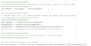
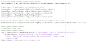
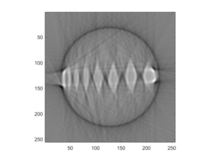
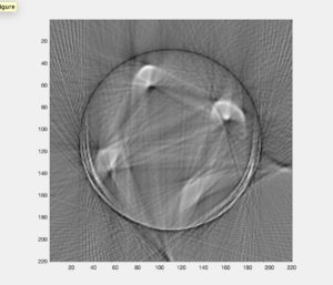
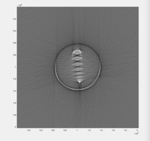
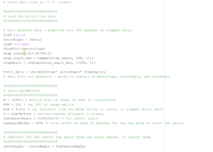
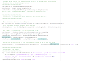
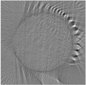
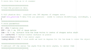
This week we were able to complete the assembly of our scanner and the code to run it so that we could acquire the projection data for our first image reconstruction. The Matlab code used for the reconstruction (Fig. 1) was a modified template designed to work for these IR CT scanners, but in the reconstructed image (Fig. 2) it is impossible to tell which phantom was used. This poor image quality was likely a result of either our method of acquiring the projection data, the reconstruction algorithm, or some other external influence on the system. In any of these cases, we hope to resolve the issue and complete scans and reconstruct images for all the different phantoms with reasonable image quality by the end of the next week.


Figure 1. MATLAB code for fan-beam reconstruction of real projection data

% recon data from an ir ct scanner


%%%%%%%%%%%%%%%%%%%%%%%%%%%

% load the projection data

%%%%%%%%%%%%%%%%%%%%%%%%%%%


% full phantom data – acquired over 360 degrees of stepper motor

load servoangle; % data file you generate – needs to contain diodeVoltage, servoAngle, and stepAngle

load step

load voltage

%%%%%%%%%%%%%%%%%%%%%%%%%%%

% recon parameters

%%%%%%%%%%%%%%%%%%%%%%%%%%%

N = 200; % matrix size

FOV = 14; % cm, FOV of image matrix

Dcm = 6.9; % cm, distance from fan beam vertex to center of stepper motor shaft

D = Dcm*N/FOV; % vertex->center distance in pixels

fanCenterAngle = 80; % fan center angle 

fanAngleWidth = 90; % total width we need in degrees for the fan beam to cover the object


%%%%%%%%%%%%%%%%%%%%%%%%%%%

% subtract off the center fan angle from the servo angles, to center them

%%%%%%%%%%%%%%%%%%%%%%%%%%%

servoAngle = servoAngle – fanCenterAngle;


%%%%%%%%%%%%%%%%%%%%%%%%%%%

% reshape data into a fan beam sinogram matrix. We assume that servo angle

% is minor dim in diodeVoltage vector

%%%%%%%%%%%%%%%%%%%%%%%%%%%

nServoAngles = length(unique(servoAngle));

nStepAngles = length(unique(stepAngle));

fanBeamData = reshape(diodeVoltage,[nServoAngles,nStepAngles]);


%%%%%%%%%%%%%%%%%%%%%%%%%%%

% interpolate along the fan beam dimension to center the data

%%%%%%%%%%%%%%%%%%%%%%%%%%%


% find increment between servo Angles

deltaServoAngle = abs(diff(unique(servoAngle)));deltaServoAngle = deltaServoAngle(1);

% find increment between stepper motor angles

deltaStepAngle = abs(diff(unique(stepAngle)));deltaStepAngle = deltaStepAngle(1);


% get input (I) and output (O) interpolation grids

servoAnglesI = min(servoAngle):deltaServoAngle:max(servoAngle);

stepAngles = min(stepAngle):deltaStepAngle:max(stepAngle);

[stepAnglesI,servoAnglesI] = meshgrid(stepAngles,servoAnglesI);

servoAnglesO = -fanAngleWidth/2:fanAngleWidth/2;

[stepAnglesO,servoAnglesO] = meshgrid(stepAngles,servoAnglesO);


% do the 2D interpolation to the centered grid that we will use for recon

fanBeamDataCent = interp2(stepAnglesI,servoAnglesI,fanBeamData,stepAnglesO,servoAnglesO,’cubic’,0);


%%%%%%%%%%%%%%%%%%%%%%%%%%%

% reconstruct the image

%%%%%%%%%%%%%%%%%%%%%%%%%%%

img = ifanbeam(fliplr(fanBeamDataCent),D,’fancoverage’,’cycle’,’fanrotationincrement’,…

    deltaStepAngle,’fansensorgeometry’,’arc’,’fansensorspacing’,1,…

    ‘filter’,’Ram-Lak’,’frequencyscaling’,1,’interpolation’,’nearest’,…

    ‘outputsize’,N);

figure;imagesc(-img);axis image;colormap gray


Figure 2. Reconstructed image from real projection data
image

Question: What parameters of your scanner and scan method influence resolution? Investigate these. 

Answer: Our resolution for these IR CT scanners is determined by the data acquisition rate set by the arduino, the step angle of the servo arm, and the step angle of the stepper motor. Assuming that the arduino baud rate is sufficient, the stepper motor would be the limiting factor of resolution because it has a minimum step angle of 1.8 degrees while the servo arm can move just 1 degree per step.

IR CT Scanner Week 5

Blog Post Week #5

Aayush Gupta & Hunter Spivey


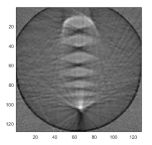
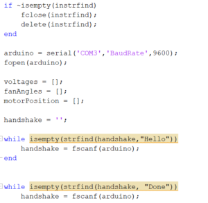
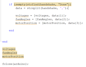
This week we were finally able to reconstruct the data obtained from the Arduino and obtain a reconstructed image from the stepper and servo data of our CT scan. The MATLAB code used to parse the data and produce an image is displayed below, with appropriate comments included:
Matlab Code Week 5 #1

Matlab Code Week 5 #2

Matlab Code Week 5 #3

A problem we faced while trying to produce our reconstructed image was that initially we set our stepper motor to record 201 voltage values per revolution instead of 200, which led to a sinogram that was tilted. After we realized our error, we modified our code and got the image below for our phantom:

Reconstructed IR CT Class Image

The question that we sought to answer this week were:
Q: Do all the features in your phantom images have the correct size? If not, why? Are their sizes accurately represented in all dimensions?

A: No they do not, our reconstructed image is a phantom that is significantly less geometric than our original phantom- our original’s dips and crevices were much straighter than shown in the reconstructed image. However, for the most part they resemble one another, with the only difference being that the image was not as detailed and did not include many of the more difficult detail


Hopefully next week we can quantify image errors discretely and discern to what extent our reconstruction correlates to the original phantom.

IR CT Week 5 Update

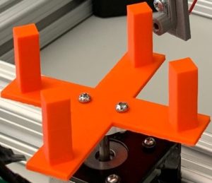
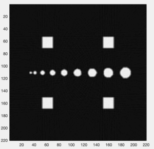
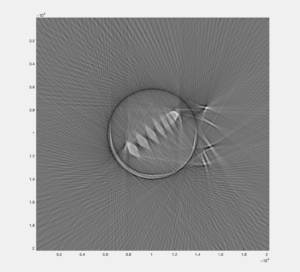
This week the group imaged a new phantom and tested changes to the image reconstruction parameters.  Ultimately the tweaking of parameters led the group back to their original inputs as shown in the week 4 blog post.  The baud rate was also adjusted to 14400 to smooth the motion of the servo motor but no improvement was noticed in image quality.  Attached below is the new phantom and resulting image output.  The larger phantom caused issues with resolving the image closer to the edges of the field of view and resulted in blurrier imaging of the posts that in prior phantoms which were smaller and more centrally concentrated.

Fig 1.The new phantom to be imaged

IR CT new phantom real

Fig 2. The resulting IR CT image of the new phantom

IR CT new phantom

Question:

What happens if you more coarsely or finely sample the stepper motor position?

The increase in number of polar steps from moving the stepper more finely results in a higher resolution image with more data points.  If moved more coarsely then the resultant image has fewer data points collected and therefore a lower power to resolve small objects.


Blog Post Week #5: Imaging Instrumentation Infrared CT Lab

Jorie Budzikowski, Stephanie Molitor, and Rachel Welscott

This week we were able to work on:

  1. Imaging various phantoms
  2. Changing image collection parameters including step size, light around the detector, field of view, etc.

1. Imaging Various Phantoms

Last week we were able to complete our servo, stepper motor, and Arduino code. We also were able to complete the image reconstruction of our first phantom. This week we aimed to continue to gather data with different phantoms and altered parameters on the image reconstruction script including the field of view, fan angle width, and distance from the center of the phantom to the servo motor to get a clear image. Some of the relevant image parameters we aimed to investigate were the image resolution, the smallest detectable line pair, image artifacts, and image scale size. The actual code changes for this week are minimal, but the changes to the sinogram and the corresponding phantom image were significant.

We were able to make reconstructions of three different phantoms, shown below. The overall quality of these reconstructions is decent, as we were able to discern the general shapes and spacing. However, some distortions were present, such as blurring of edges that turned square shapes more round. Additionally, we found the second phantom (middle image below) produced the least clear reconstruction. We found that this was due to the outer four pegs blocking the IR light from the inner pegs. Since our CT scanner only took images in one direction at a time, this altered our final reconstructed image.

different phantoms

Image 1: The three different phantoms we were able to produce images of using our Infrared CT scanner system.
2. Changing Image Collection Parameters
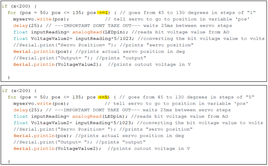
We also changed the step size for both the servo and the stepper motor to determine how the step size correlated to image resolution. We changed the servo step size from 1 to 5 degrees, and changed the stepper motor from 1.8 to 3.6 degrees. We were able to change the step size very easily, by only changing one value in our Arduino code, as shown below. We determined that an increased step size for both the servo and of the stepper motor resulted in a decreased image resolution, as illustrated in the following image reconstructions.

bad recons

Image 2: Increasing the servo step size (left) and increasing the stepper motor step size (right), both had the effect of decreasing image resolution.

servo

Image 3: The Arduino code, showing the parameter changes to alter the step size of the servo from a step size of 1 (top) to a step size of 5 degrees (bottom).

stepper

Image 4: The Arduino code, showing the parameter changes to alter the step size of the stepper motor from a step size of 1.8 (top) to a step size of 3.6 degrees (bottom).

The next parameter we changed was the lighting around our detector. We were working by the window, so we found that the generated sinogram showed different colors on the window side and classroom side of the image. This would impact the resolution of our image reconstructions by changing the grayscale coloring of the phantom. By covering our CT scanner with jackets to block the light during the collection, we were able to eliminate this variability in coloring of the image due to the lighting and produce a more consistent ambient environment signal.
Additionally, one of the artifacts that we noticed in our reconstruction was a dark ring around the outside of each phantom (see Image 1). We believe that this was due to a high level of noise at the upper end of our fan angle. This is easily seen by the blue stripe on the far right of our sinograms. By cropping the fan angle in our reconstruction to only capture the bulk of the sinogram, we were able to make this dark ring less apparent.

sinograms

Image 5: Two sinograms produced from an unlit (left) environment and an environment with ambient light (right). Both sinograms feature a dark blue stripe on the far right, which is what produced the dark ring around our image reconstructions.

The questions that we aimed to answer in this lab are as follows:

  1. What is the smallest feature or line pair that you can resolve?
    1. The smallest gap between phantom pegs that we were able to resolve in our image reconstruction was measured to be 0.445 inches.
  2. What happens if you more coarsely or finely sample the fan beam angle and/or stepper motor positions?
    1. Last week, we hypothesized that a smaller step size for the servo and stepper motor would produce finer spatial resolution. This week, we were able to test our hypothesis and found that we were correct, as increasing the step size of each resulted in a very poor image reconstruction.

Infrared CT Update 4: February 4, 2020

Morgan Kinney, Tanner Hoppman, Jude Franklin

This week we spent much of our time troubleshooting an issue with an unknown cause, which we finally resolved with the discovery that our IR LED no longer functioned. This issue was seen in the fact that our serial monitor did not output changing values as the the distance between our LED and diode was varied. Once confirming that our emitter-detector system was working and being measured properly, we programmed the arduino to print to the serial monitor the three values we will need for reconstruction: voltage measurement, servo angle, and stepper angle. We were also able to finish our reconstruction program in matlab and test it on sample projection data to obtain an image (Fig. 1-2). The last steps to being able to reconstruct to an image will be modifying the scan parameters for the servo and stepper motors to get the best image and transferring the data into Matlab.

Figure 1. MATLAB code for fan-beam reconstruction of sample projection data

clear all

load fanBeamProjectionData

theta1=reshape(stepperAngle,269,360);

voltage1=reshape(voltage,269,360);

[rad, xp]=radon(voltage1,theta1(1,:));

figure(1)

imagesc(theta1(1,:),xp,voltage1)

colormap(hot)

colorbar


N = 220; % matrix size

FOV = 10; % cm, FOV of image matrix

Dcm = 7.78; % cm, distance from fan beam vertex to center of stepper motor shaft

D = Dcm*N/FOV; % vertex->center distance in pixels


figure(2)

img = ifanbeam(voltage1,D,’FanSensorSpacing’,.5,’OutputSize’,N);

imagesc(img);axis image;colormap gray


Figure 2. Reconstructed image from sample projection data

samplerecon1

Question: Which way does your photodiode need to be oriented to get a positive output voltage?

Answer: The photodiode needs to be oriented with the positive end connected to ground and the negative end connected to the inverting input of the op amp. This allows for the negative current through the photodiode to be powered by the op amp from the output to ground.

Feb 4th Blogpost

Alex Boyd, Maggie Ford, and Myron Mageswaran


The construction of the actual scanner was completed in previous labs, so the past week was spent mostly collecting data and then polishing the MATLAB code to try to improve the reconstructed image.  The first image collected (Image 1) was overall somewhat clear, but for a portion of the collection, the photodiode was unplugged, so the image contains a blurry spot from the incorrect data points.  Students then took another complete data set to use for the reconstruction. This new image (Image 2) was very clear, but had a bit of a ring around the object.  To correct this, students remeasured, adjusted, and tested the FOV and other parameters and used the best corresponding values.  

Screen Shot 2020-01-28 at 11.35.39 AM

Image 1: The first image students reconstructed using the data set that had the photodiode disconnected for a portion of time evidenced by the region circled on the right side

Screen Shot 2020-01-28 at 12.13.16 PM

Image 2: The new image students reconstructed using the complete data set 


MATLAB CODE: Below is the code that students used for the reconstruction of the images with comments to follow along


%Reconstruction of an Infrared CT Scanner


%%%%%%%%%%%%%%%%%%%%%%%%%%%

% load the projection data

%%%%%%%%%%%%%%%%%%%%%%%%%%%


% full phantom data – acquired over 360 degrees of stepper motor

load phantom2Trial1.mat; % data file you generate – needs to contain diodeVoltage, servoAngle, and stepperAngle


%%%%%%%%%%%%%%%%%%%%%%%%%%%

% recon parameters

%%%%%%%%%%%%%%%%%%%%%%%%%%%

N = 20200; % matrix size

FOV = 17.45; % cm, FOV of image matrix

Dcm = 7.78; % cm, distance from fan beam vertex to center of stepper motor shaft

D = Dcm*N/FOV; % vertex->center distance in pixels

fanCenterAngle = 80; % fan center angle 

fanAngleWidth = 100; % total width we need in degrees for the fan beam to cover the object


%%%%%%%%%%%%%%%%%%%%%%%%%%%

% subtract off the center fan angle from the servo angles, to center them

%%%%%%%%%%%%%%%%%%%%%%%%%%%

servoAngle = servoAngle – fanCenterAngle;


%%%%%%%%%%%%%%%%%%%%%%%%%%%

% reshape data into a fan beam sinogram matrix. We assume that servo angle

% is minor dim in diodeVoltage vector

%%%%%%%%%%%%%%%%%%%%%%%%%%%

nServoAngles = length(unique(servoAngle));

nStepAngles = length(unique(stepperAngle));

fanBeamData = reshape(diodeVoltage,[nServoAngles,nStepAngles]);

% potVoltage = reshape(potVoltage,[nServoAngles,nStepAngles]);


%%%%%%%%%%%%%%%%%%%%%%%%%%%

% interpolate along the fan beam dimension to center the data

%%%%%%%%%%%%%%%%%%%%%%%%%%%


% find increment between servo Angles

deltaServoAngle = abs(diff(unique(servoAngle)));

deltaServoAngle = deltaServoAngle(1);

% find increment between stepper motor angles

deltaStepAngle = abs(diff(unique(stepperAngle)));

deltaStepAngle = deltaStepAngle(1);


% get input (I) and output (O) interpolation grids

servoAnglesI = min(servoAngle):deltaServoAngle:max(servoAngle);

stepAngles = min(stepperAngle):deltaStepAngle:max(stepperAngle);

[stepAnglesI,servoAnglesI] = meshgrid(stepAngles,servoAnglesI);

servoAnglesO = -fanAngleWidth/2:fanAngleWidth/2;

[stepAnglesO,servoAnglesO] = meshgrid(stepAngles,servoAnglesO);


% do the 2D interpolation to the centered grid that we will use for recon

fanBeamDataCent = interp2(stepAnglesI,servoAnglesI,fanBeamData,stepAnglesO,servoAnglesO,’cubic’,0);


%%%%%%%%%%%%%%%%%%%%%%%%%%%

% reconstruct the image

%%%%%%%%%%%%%%%%%%%%%%%%%%%

img = ifanbeam(fliplr(fanBeamDataCent),D,’fancoverage’,’cycle’,’fanrotationincrement’,…

    deltaStepAngle,’fansensorgeometry’,’arc’,’fansensorspacing’,1,…

    ‘filter’,’Ram-Lak’,’frequencyscaling’,1,’interpolation’,’nearest’,…

    ‘outputsize’,N);

figure;imagesc(-img);axis image;colormap gray


Question 1:

What happens if you more coarsely or finely sample the stepper motor positions?  The finer the stepper motor position, the higher resolution of the image because there are more data points.

Blog Post Week #4: Imaging Instrumentation Infrared CT Lab

Blog Post Week #4: Imaging Instrumentation Infrared CT Lab                                   Jorie Budzikowski, Stephanie Molitor, and Rachel Welscott

(overheard) QUOTE OF THE WEEK:                                                                         “Have you ever seen a CT scanner without a hood on it?”                                                “…Yes we had to watch that for THIS class”

Because of our progress last week with optimizing the servo and stepper motor’s rotation, we were able to make progress this week on:

  1. Matlab code to collect the voltage and position vectors needed for image reconstruction
  2. Image reconstruction in Matlab

1. Collecting the voltage and position vectors in Matlab


Our arduino code that controls the stepper motor and servo rotation also prints their positions and the voltage values collected at each position. Moving into Matlab, our code reads off of the serial monitor from the arduino and produces a single vector with values that alternate the servo angle and the diode voltage at that position. We were then able to extract the position and the voltage values from that vector by taking the values for either the even or odd indices. Image one shows the actual code that is used to collect the vectors. These are the two vectors (theta and voltage) that are necessary to reconstruct the image. Additionally, we manually constructed a vector of our relative stepper motor angles by using the step size of 1.8 degrees that we previously calculated. 

It takes about 10 minutes to collect a complete dataset, as the servo motor scans the phantom 200 times, once for each step of the stepper motor to complete a 360 degree turn. This results in a total vector length of 17,200 data points for each of the three (servo angle, stepper angle, and voltage) vectors. We completed this data acquisition in class. 

Video 1: Stepper and servo motor rotating during data collection

IMG_2152 (1)

2. Image reconstruction in Matlab

Using the template for image reconstruction in Matlab, we were able to input our data collected for voltage, stepper angle, and servo angle along with some physical constraints of our system and desired output image. We had to convert our single detector voltages into fan beam data in order to reconstruct the sinograms from our voltages. From here, we simply used the radon function in Matlab to convert our sinograms to an image. The reconstructed image still has some slight parameter changes necessary to optimize the image, however the output image looks like our phantom! We will continue to alter the fan center angle and width to increase resolution, and  test our system on other phantoms in the upcoming week.

Image 1: Code for the Matlab reconstruction (using template)

image 1

image 2

Image 2: The reconstructed image of the phantom

image 3


Questions

    • Image Errors
      • Question: Do all the features in your phantom images have the correct size? If not, why? Are their sizes accurately represented in all dimensions?
        • No, not all the features in the phantom image have the correct size. Our phantom image is much more rounded than the rectangular extrusions of our phantom. The overall size and spacing of our phantom image reflect our actual phantom, but the fine details (especially corners) are distorted.
    • Artifacts and Resolution
      • Question: What happens if you more coarsely or finely sample the fan beam angle and/or stepper motor positions?
        • Currently, the stepper motor has a step angle of 1.8 degrees and our servo has a step angle of 1 degree for each measurement taken. This makes our stepper motor the limiting factor with spatial resolution. We think that by more finely sampling the servo, we would see no change in image resolution because the servo is not the current limiting factor. However, by  more finely sampling the stepper motor, we would be able to increase the spatial resolution of our image and perhaps better image the finer details of our phantom.

IR CT Scanner Week 4

Week 4 Update:

Hunter Spivey and Aayush Gupta


This week unfortunately didn’t see as much progress as we would have liked, because we discovered that in order to begin interfacing our arduino output with matlab, we would need to download a newer version of matlab as the version we were using was too old. This took the majority of class time on tuesday, and with the mechanical portion of our scanner done, this limited the progress we could make. Thursday was more productive, and I managed to finish the arduino code to output the data in a way that could be easily received, delineated, and stored by matlab. I also began our matlab code that actually received and organized this data. Next week we plan to begin the reconstruction code and try to construct the first image of our phantom. If this goes well, we may be able to try and tweak our system to improve the imaging process.

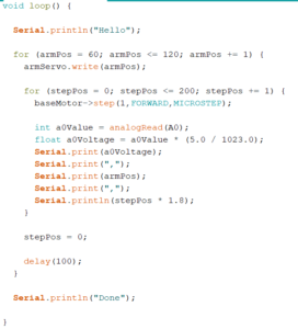
Arduino Code:

Arduino code week 4

Matlab Code:

Week 4 matlab code #1

week 4 matlab code #2

Question:

    • Why is the fan2para() function needed

Answer:

  • Our imaging configuration is a fan beam configuration and thus the data we read in needs to be converted to parallel coordinates before we can use iradon() to reconstruct the projections into images.


CT Scanner Week #4 – 1/31/2020

Week #4

Javier and Nicholas J. Holden

This week consisted of a lot of frustration. Whenever we fixed our servo, the stepper would stop working. When the stepper was fixed, the servo would stop working. We thought there may be a shortage somewhere on the Arduino with a wire touching the board. We also edited the code significantly to see if the issue was code-based and resorted to using the example stepper and servo motor code as a baseline test. The final solution ended up being restarting the Arduino multiple times and crossing our fingers. The solution worked. Upon fixing the system, we rewrote the Arduino code for increased resolution by decreasing both stepper and servo angle to one-degree rotation per sweep and fixing of the rotation of the stepper such that it would rotate fully for each angle of the servo sweep. Once this was done, we then began the process of gathering the data from a full sweep of the CT and importing and saving the data into Matlab. 

The next step was to measure and input the different inputs in MATLAB in order to create the reconstructed model of our phantom. The code would be based on the CT recon template provided by Dr. Grissom. 

Question: What is the fan angle of your scanner? How many projections will you acquire across this angle, given the resolution with which you can move your servo?

Answer: The fan angle of our scanner was 140 – 55 = 85 degrees. We plan to acquire 17,000 projections. This number was gathered by multiplying the fan angle by the stepper angle. 85 * 200 = 17,000!

It was a short week, but it was filled with a lot of problem solving and adventure. Something that Javier and Nicholas J. Holden aren’t afraid to seek out!

The video below demonstrates the stepper and servo in action collecting data points.

IMG_1047

Below is the code for our Arduino. This update correctly causes our servo and stepper to function. We did two sweeps to increase our Signal-to-Noise ratio.

#include <Servo.h>

#include <Wire.h>

#include “utility/Adafruit_MS_PWMServoDriver.h”

#include <Adafruit_MotorShield.h> 


// Setting up pins and angles for the motor

int servopin = 10;

Servo servo;

int angle = 0;


// Create the motor shield object with the default I2C address

Adafruit_MotorShield AFMS = Adafruit_MotorShield();

// Connect a stepper motor with 200 steps per revolution (1.8 degree)

// to motor port #2 (M3 and M4) 

Adafruit_StepperMotor *myMotor = AFMS.getStepper(200, 2);


void setup() {

  // Opens the serial port

  Serial.begin(9600);

  AFMS.begin();  // create with the default frequency 1.6KHz

  // Sets up setting for the servo and stepper motor

  servo.attach(servopin);

  myMotor->setSpeed(60);  // 10 rpm  

}


void loop() {

  // Signals to Matlab to begin the collection of data

  Serial.println(“Start”);

  // Increments through servo angle one at a time

  for(angle=55; angle<140; angle+=1){

    servo.write(angle);

    delay(15);

    // Full rotates stepper and gathers data at each stepper angle

    for(int step=0; step<200; step+=1){

      double sensorvalue = analogRead(A2);

      double pot = analogRead(A3);

      Serial.print(step);

      Serial.print(“,”);

      Serial.print(angle);

      Serial.print(“,”);

      Serial.print(sensorvalue/1023*5);

      Serial.print(“,”);

      Serial.println(pot/1023*5);

      myMotor->step(1, FORWARD, MICROSTEP); 

    }

  }

  // Increments through servo angle one at a time

  for(angle=140; angle>55; angle-=1){

    servo.write(angle);

    delay(15);

    // Full rotates stepper and gathers data at each stepper angle

    for(int step=0; step<200; step+=1){

      double sensorvalue = analogRead(A2);

      double pot = analogRead(A3);

      Serial.print(step);

      Serial.print(“,”);

      Serial.print(angle);

      Serial.print(“,”);

      Serial.print(sensorvalue/1023*5);

      Serial.print(“,”);

      Serial.println(pot/1023*5);

      myMotor->step(1, FORWARD, MICROSTEP); 

    }

  }

  // Signals to Matlab to end the collection of data

  Serial.println(“End”);

  delay(10000);

}


IR CT Scanner Update #4

Update #4

Danielle, Antonio, Hannah

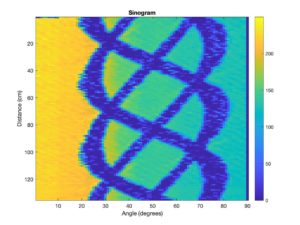
This week, we captured our CT data in a text file and reconstructed it. The shape of our sinogram looks accurate, but there is higher intensity light observed at lower degrees (0 to 30 degrees), which is indicated by the yellow color, and lower intensity light observed at higher degrees, which is indicated by the aqua color. These findings show that one side of the CT scanner is more exposed to light, probably from the classroom window, than the opposite side. Our reconstructed image looks somewhat accurate, but we suspect that our measurements are undersampled. Next week, we will increasing the number of samples/time period and will collect data with the blinds closed and a tarp covering the scanner. Below are images of our sinogram and reconstructed image.

sinogram

Figure 1: Sinogram

Reconstructed Image

Figure 2: Reconstructed image

Question: What parameters of your scanner and scan method influence resolution? Investigate these.

We have the servo motor moving the swing arm 90 degrees and the stepper motor moving once when the swing arm finishes its rotation. We should switch the order of the servo motor and the stepper motor so that the stepper motor rotates 270 degrees and then the swing arm moves once. This would increase the resolution because the stepper motor is more stable than the servo motor, so it would reduce the probability of motion artifacts.

We also expect the size of our detector and the distance between the fan beam and motors to affect our resolution. We plan to investigate all of these parameters next week and see how the resolution improves.