Infrared CT Update 3: January 28, 2020

Morgan Kinney, Tanner Hoppman, Jude Franklin

This week we were able to connect the motors to our Arduino circuit. We spent our time programming both the stepper motor and servo arm to work in tandem. This was particularly tricky because we had to refine their range of motion, but we had issues with getting their code to work without interfering with each other. When adding the stepper motor, the normally functioning servo started malfunctioning. We concluded this week with fully functioning code for all the mechanical components as seen in the video under Element 1 and the image of the Arduino code in Element 2. The next step will be to code the matlab programming for the imaging of the scanner itself.

Element 1: Video of functioning servo arm and stepper motor

servoarmsteppermotor

Element 2: Image of Arduino code to program the moving parts

imagingcode128

Question: Why is the fan2para() function needed?

Answer: The projection data obtained from our IR CT device is fan-beam projection data, and the matlab program is set up to reconstruct parallel beam projections. Thus, fan2para is needed to convert our data from fan-beam to parallel beam in order to be reconstructed into the final images.

IR CT Update #3

Update #3 

Danielle, Hannah, Antonio

    Last week we predominantly worked on the software and data acquisition. Because we were having difficulty with the serial communication between the Arduino and Matlab, we decided to write Python code that would perform the serial communication instead. Below is the Python code that communicates with the Arduino from the serial port. The Python code reads successive lines from the serial port as the Arduino is taking data and then stores the projection angle data into the array byte_data. Because the data the Arduino prints to the serial port is in byte form, the script decodes the byte data, splits the values after each comma, and then stores them in an array. Once all of the data is received, this code writes the array to a text file on the users computer in ASCII format which is important. Because the text file is in ASCII format, matlab can very easily load the data from the text file directly into an array using the load() command. From here, the matlab code below can be used to perform filtered backprojection and reconstruct the image.

Question

What is the finest resolution with which you can move the swing arm (servo) and stage (stepper motor)? What does this dictate about the finest spatial resolution of your image

The finest resolution with which we can move the servo is 1.8 degrees and for the stage, 200 steps per resolution. This means that the finest spatial resolution is determined by whichever component has the largest angle of rotation.

Question

The servo has an extra (white) wire on it, that reads out its built-in position potentiometer, which you can use to record the servo’s actual position (rather than just its intended position). Is your image reconstruction improved by using this value instead of the intended value? 

Our image reconstruction is improved.

Our Python code

Screen Shot 2020-01-27 at 11.19.52 PM

Our Matlab code

Screen Shot 2020-01-27 at 11.20.01 PM

IR CT Week 3 Update

Alex Boyd, Myron Mageswaran, Maggie Ford

This week the group refined the cable management and secured the arduino and breadboard to the scanner frame (shown below). The group also increased the fan angle to now sweep 100 degrees in order to image the entire phantom.  The position of the stepper motor and servo are now being read by MATLAB and being placed in individual vectors for interpretation by the image reconstruction script.  Lastly, the image reconstruction script parameters were set by the group.  The students still need to set the inputs to the final image creation function but the initial parameters have been set as seen below.


Input Parameters for Reconstruction

Screenshot (2)

Refined Cable Management

IR CT Scanner

Question: What parameters of your scanner and scan method influence resolution? Investigate these.

  • The size of the servo step between reads influences resolution as well as the distance between the photodiode and IR LED because this changes the focus by changing the scatter angles that are read by the system.

Question: What is the smallest feature or line pair that you can resolve?

  • The actual smallest feature we can resolve will be found (and this answered again next week) when an image is constructed but the resolution will be limited by those factors mentioned in the above question such as servo step size and the size of the focal point of the photodiode.

IR CT Scanner Week 3 Update

Hunter Spivey and Aayush Gupta:

This week be managed to connect our stepper motor to our adafruit motorshield via the M1 and M2 ports and run it via our arduino code. We initially had connected it via the digital pins, but eventually rewired it. Following this we began to work on reading our output from out current-to-voltage converting circuit into our arduino’s analog input, and displaying it on arduino’s built in serial monitor. We were able to successfully do this, and we confirmed that the displayed values would change if we blocked the incident IR light on the photodiode. After this we then moved on to connecting our fan arm servo to the arduino board, and writing the code to move it in the correct direction. We initially struggled to connect the servo properly, but after working with it for a bit, were able to connect it and write the code to move it over a specified angle. Finally we worked on cleaning up our wire connections to make it a little bit tidier and less all over the place.

Our next goal is to work on interfacing the arduino serial monitor output with Matlab so we can use the measured voltage values to try and reconstruct an image of the phantom.

Video:

Below is a video of where our scanner was at when we finished by the end of last week. We have changed the code so that the stepper motor only takes one step per sweep of the fan arm, although this video does not reflect this change.

IMG_3048

Code:

Additionally, we have modified the code to be cleaner, as well as to address the change in the stepper motor previously described. Images of the new code can be found below.

Week 3 Code #1Week 3 Code #2

Question: 

The servo has an extra (white) wire on it, that reads out its built-in position potentiometer, which you can use to record the servo’s actual position (rather than just its intended position). Is your image reconstruction improved by using this value instead of the intended value?

Answer: 

Because this would give us the actual position of the fan arm as opposed to what we told it it should be at, then yes, using the white feedback wire could potentially improve the accuracy of our servo’s position recording. However, since we are not moving the fan arm at a very high rotational speed, the use of this more accurate feedback wire isn’t necessary as our servo should have more than enough time to reach the position we instruct it to. If the servo as a whole is off on its positioning, then it could become an issue, but for our current purposes it isn’t required.


Infrared CT Scanner Update 3

Blog Post Week #3: Imaging Instrumentation Infrared CT Lab
Jorie Budzikowski, Stephanie Molitor, and Rachel Welscott

Quote of the Week:

“Do you know what this delay is for?”
“I don’t know, but it’s probably not important. You can delete it.”
*deletes delay*

“OKAY so that delay was VERY important!”

This week, we were able to tackle several parts of the Infrared CT Scanner including the servo rotation, the stepper motor rotation, and the Matlab readout of photodiode voltage from the Arduino.

The Servo and Stepper Rotation:

With the success of the voltage readouts from our circuit, we have since turned our attention to the Servo that controls the rotating arm of the scanner. We have programmed the Servo (via Arduino) to move the rotating arm, and have optimized the speed and delay during rotation. The code that controls the Servo rotation is shown in the image below. We have also programmed the stepper motor to move the phantom with a step size of 1.8 degrees between each full sweep of the servo arm. To complete a full 360 degree image of the phantom, the stepper motor must rotate the phantom 200 times. The combined movements from the Servo and the stepper motor are shown in the video below. We have also altered the Arduino code to display the output voltage and sweeper arm position on the serial monitor for each data point.

Video one: The Servo has been programmed to rotate the sweeper arm around the phantom, and the stepper motor takes (very small) steps between each full sweep.

Image One: The Arduino code that controls both Servo and stepper motor rotation. This code also writes the output voltage and corresponding sweeper arm position to the serial monitor.

combined code

The Matlab readout of the photodiode voltage from the Arduino:

Matlab is a crucial element to this CT Infrared Scanner because it is the way that we will ultimately analyze the results from our scan. Our code should read out and store the voltage value at each point for both the sweeper arm and gantry rotation. These readout values will be translated into binary numbers and be displayed as black or white on our image reconstruction. Our preliminary code, shown below, is used to read and store the output voltage for each step of our Servo and stepper motor.

Image Two: The Matlab code that stores the output voltage value for each step.

matlab

Questions we set out to answer this week:

  1. What is the finest resolution with which you can move the swing arm (servo) and stage (stepper motor)? What does this dictate about the finest spatial resolution of your image?
    1. The smallest step size that we can take with the stepper motor is 1.8 degrees. The smallest step size we can take with the servo is 1 degree. This dictates that the finest spatial resolution of our image is 1.8 degrees since this is the larger of the two component resolution values.
  2. The servo has an extra (white) wire on it, that reads out its built-in position potentiometer, which you can use to record the servo’s actual position (rather than just its intended position). Is your image reconstruction improved by using this value instead of the intended value?
    1. The position value of the servo is an arbitrary position value. As long as we know where the designated 0 position is located, it does not really matter whether or not we know the actual position of the servo. Thus, the white wire does not add much information to our system.
  3. What parameters of your scanner and scan method influence resolution? Investigate these.
    1. The parameters that influence resolution are the step size of the servo motor and the time the servo motor has to record a section of the “image” in between steps.

CT Scanner Week #3 – 1/24/2020

Javier and Nicholas J. Holden

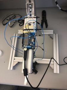
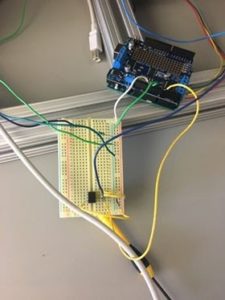
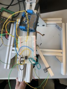
This week, we tried to make our work more aesthetically pleasing and efficient by securing the wires as well as both the breadboard and Arduino to the metal bar above the servo. The breadboard was fashioned with a double-sided adherence tape and the Arduino was with Velcro. This allows the ability to attach and detach the Arduino which is useful. In addition, many wires were shortened and also shrinking tape was attached to the various junctions to not leave those connections exposed.

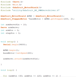
We encountered the problem of the servo shaking in place and not moving. The problem was solved by reworking part of the code written for it and moving a pin to a different analog input. It now works as intended; however, as one problem ends, another begins. The stepper is our primary challenge. While all the correct wires are attached to our Arduino, the code is not allowed to run. Many solutions were attempted such as just moving utilities into the folder to allow the code to work as well as running the test code. In a desperate attempt, we disconnected our servo from our stepper. With this connection severed, the stepper began to rotate as programed below. It was concluded that for some reason our servo was interfering with our stepper. The working theory is that the servo may be drawing too much current. Our solution was to install a new servo and see if that will work. But before that solution was carried out, we noticed that the servo control wire may be stealing tons of current. So we attempted to resolder and attach the control wire back into the 3 pin set up because the control wire wasn’t connected to the power wires. This did not work, so the original solution to replace the servo was taken. \

Unfortunately, when we added the new servo, we encountered the same problem again: the stepper stopped rotating. Our next idea was to restart the Arduino. This still did not fix anything. In an absolutely desperate attempt, we had to use a different pin for our potentiometer from the servo. That was the problem. However, this solution broke the servo. We believe the same issue is at play though and so only need to find another analog pin to get the system to work.

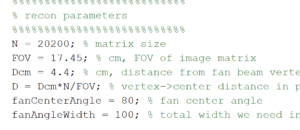
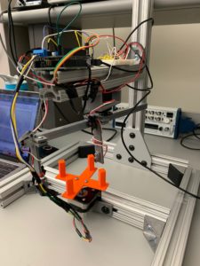
Below are an attached photo and video of the updated machine. Photo 1 is a picture of the current system. There is a marked improvement to the design compared to last week. Video 1 displays the servo and stepper in action. After many weeks, we have finally achieved the desired function from both of the devices. Our next steps are to fine-tune the system and create MATLAB code to be able to do reconstruction for the information collected from the photodetector as well as fine-tune the Arduino code for this same process. The Arduino code needs to be updated to better replicate the fan angle as well as provide measurements for each of the fan angle. 

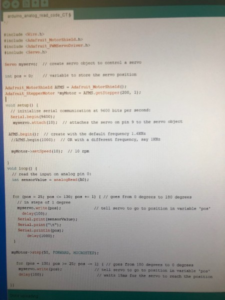
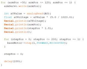
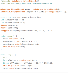
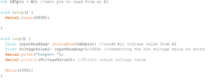
Below is our code for the Servo motor and the Stepper

#include <Servo.h>

#include <Wire.h>

#include “utility/Adafruit_MS_PWMServoDriver.h”

#include <Adafruit_MotorShield.h> 

int servopin = 9;

Servo servo;

int angle =0;


// Create the motor shield object with the default I2C address

Adafruit_MotorShield AFMS = Adafruit_MotorShield();

// Connect a stepper motor with 200 steps per revolution (1.8 degree)

// to motor port #2 (M3 and M4) 

Adafruit_StepperMotor *myMotor = AFMS.getStepper(200, 2);


void setup() {

  // put your setup code here, to run once:

  Serial.begin(9600);

  servo.attach(servopin);

  AFMS.begin();  // create with the default frequency 1.6KHz

  myMotor->setSpeed(60);  // 10 rpm  

}


void loop() {

  // put your main code here, to run repeatedly:

  for(angle=70; angle<230; angle++){

    servo.write(angle);

    double sensorvalue = analogRead(A2);

    double pot = analogRead(A3);

    Serial.print(sensorvalue/1023*5);

    Serial.print(“,”);

    Serial.println(pot/1023*5);

    myMotor->step(50, FORWARD, MICROSTEP); 

    delay(50);

  }

  for(angle=230; angle>70; angle–){

    servo.write(angle);

    double sensorvalue = analogRead(A2);

    double pot = analogRead(A3);

    myMotor->step(50, FORWARD, MICROSTEP); 

    Serial.print(sensorvalue/1023*5);

    Serial.print(“,”);

    Serial.println(pot/1023*5);

    delay(50);

  }

  delay(1000);

}

Photo 1 - Improved CT System

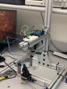
Photo 1 – Improved CT System

Please click the link to the right to watch the video of the CT Stepper in action – IMG_1004


Question: Which way does your photodiode need to be oriented to get a positive output voltage?

Answer: In order for the photodiode to receive a positive output voltage, it needs to be oriented so that the cathode is facing the op-amp, and the anode is facing ground. You will get a positive voltage that way.

Infrared CT Update 2: January 21, 2020

Morgan Kinney, Tanner Hoppman, Jude Franklin

This week we were able to continue troubleshooting our circuits. By using a multimeter, we were able to determine if the voltage at the input and outputs of the circuit was reactive to the LED and IR photodiode (Element 1). Initially, we had the setbacks of the IR LED being shortcircuited, thus we had to re-solder the connections. After we were able to determine a proper relationship between the distance between the photodiode and the LED and their relative output voltage by changing our feedback resistor to a megaohm, we focused on uploading Arduino code to read the analog input and translate that into the Serialread function. Thus, we were able to see the live read-outs of the voltage values on the serial monitor as the IR LED and photodiode distance changed. We left off attempting to transfer the serial monitor values into Matlab where they will be much more useful for image reconstruction (Element 2).

Element 1: Placement of the breadboard and Arduino on the frame. This location will allow for the circuits to remain intact while the servo arm moves during image acquisition.

irct

Element 2: Arduino and Matlab code used to communicate serial port data with Matlab.

Arduino code:

byte incomingByte1;

void setup(){

 pinMode(2,OUTPUT);

 Serial.begin(115200);

 Serial.println(“Ready”);      

}

void loop() {

 digitalWrite(2,LOW); //turn off LED

 delay(500);

if (Serial.available() > 0) {

digitalWrite(2,HIGH); //flash LED everytime data is available

delay(500);

incomingByte1 = Serial.read(); //read incoming data

Serial.println(incomingByte1,HEX); //print data

}

}


Matlab code:

clear

clc

s=serial(‘COM7’,‘BaudRate’,115200);

fopen(s);

readData=fscanf(s) %reads “Ready”

writedata=uint16(500); %0x01F4

fwrite(s,writedata,‘uint16’) %write data

for i=1:2 %read 2 lines of data

readData=fscanf(s)

end

fclose(s);

delete(s);


Question: How can you limit current into the LED to avoid damaging it?

Answer: By connecting a resistor in series with the LED and the Arduino power source, the current of the total circuit is reduced, which decreases the chances of damaging the LED. This does, however, decrease the voltage drop across the LED, which decreases its brightness, but using a moderately low resistor value (1kOhms) allows this effect to be minimal.

1/20/20 Week #2 Update

CT Scanner Blog Post Week #2

Aayush Gupta and Hunter Spivey

This week we were able to successfully design and implement a circuit that is used to power the IR LED using the Arduino Uno’s 5V supply. Moreover, we were able to incorporate a current-to-voltage op amp circuit that converts the photodiode current into a voltage signal, which is then sampled through the Arduino. We were able to ascertain that the current-to-voltage circuit was working properly by covering and uncovering the photodiode when the system was hooked up and then by discerning, through the use of a multimeter, that when it was covered the voltage values printed on Arduino were significantly lower (0-0.5V) than those when it was left uncovered (4.3-4.5V).

In the following week we will focus on programming the Arduino to move the stepper motor and server across a certain range, as well as collecting the position versus photodiode voltage data as it moves. We will also look into producing the MATLAB script that reads the Arduino’s serial port and records the values that it receives. 

Image #1: This image shows the current-to-voltage and Arduino receptor circuits optimally set up. 

Week 2 Circuit

Image #2: This image exhibits the Arduino code needed to correctly print the voltage outputted from the op amp circuit.

Week 2 Code

Below are the answers to the questions for this week:

Question: How can you limit current into the LED to avoid damaging it?

We limited the current into the LED to avoid damaging it by inserting a current loading pin in the circuit, placed between the 5 volt output and the LED, this caused the LED to not have too much current flowing into it and remains usable.


Question: Does the value of the current-limiting component affect the amount of light you detect with the photodiode? Can you optimize that?

The value of the current-limiting resistor does affect the amount of light that is detected by the photodiode, with the presence of a higher resistor causing a less luminescent lightbulb. This can be optimized by taking into account the voltage needed to power the lightbulb and using that value figuring out what the voltage across the current-limiting resistor should be. By using that voltage and the current from the Arduino, we can easily deduce the optimal resistance value of the component.

IR CT Scanner Week 2

Alex Boyd, Maggie Ford, Myron Mageswaran

Because we previously finished our current to voltage op amp circuit, we spent a majority of our time this week programming the Arduino to move the stepper motor and servo.  We were then able to report the servo and stepper positions to the serial monitor along with the voltage output. We programmed the motors such that the servo with the IR LED and photodiode fans across the object that is being imaged and then returns to its initial position. Once the servo finishes fanning across the object, the stepper motor rotates a specified range to prepare a new view for the next time the servo fans across the object.

Next week, our focus will be to read the Arduino’s serial output using MATLAB (voltage and motor positions) in order to reconstruct our data into images. We also need to fine tune how much the stepper motor rotates each time the servo fans over the object in order to maximize spatial resolution.

Video 1:  This video shows the servo sweep the IR diode across the object that is being scanned, return the IR diode to its initial position, the stepper rotate the object a small amount, and the process repeats.  

Arduino Servo and Stepper Moving

Matlab Code: This is the code we have written to read the Arduino’s serial output and store the data as a matrix in Matlab. So far, we have only written code to read the voltage output, but we will add to the code to include motor positions as well.

% create arduino object

a = arduino(‘port’,‘board’);

% create time vector

v = zeros(500,1);

t = seconds(v);

t0 = datetime(‘now’);

% enter voltage readings into a vector as time elapses

for ii = 1:length(v)

    v(ii) = readVoltage(a,‘pin’);

    t(ii) = datetime(‘now’) – t0;

end

Question: The servo has an extra (white) wire on it, that reads out its built-in position potentiometer, which you can use to record the servo’s actual position (rather than just its intended position). Is your image reconstruction improved by using this value instead of the intended value?

Answer: Using the actual position output from the servo does not improve the image reconstruction because these values are no different than the servo’s intended position.  Therefore, we will utilize the servo’s intended position values for our purposes of this scanner.

Question: Why is the Matlab function fan2para() function needed?

Answer: The fan2para() function in Matlab is needed to convert the fan-beam projections into parallel-beam projections because the IR CT scanner has a fan-beam geometry, but filtered backprojection algorithms require parallel-beam geometry.

CT Scanner Update 2

Blog Post Week #2: Imaging Instrumentation Infrared CT Lab
Jorie Budzikowski, Stephanie Molitor, and Rachel Welscott

(overheard) QUOTE OF THE WEEK:
“You know I am just really skeptical because Dr. Grissom DID NOT say to do that.”

This week we made significant progress on our CT scanner. We completed the circuit elements of our CT scanner including the IR LED and the photodiode circuits shown in Image 1 below. Using a multimeter, were able to verify that our circuit was working correctly such that the output voltage decreased when the path between the IR emitter and the photodiode was blocked. We tuned our feedback resistor value to get readout voltages in the desired range (2-3 V with full IR exposure). We then were able to program our Arduino to report the proper output voltage value on the serial monitor. A video of this Arduino readout is shown in the first video below.

Image One: The complete IR LED and photodiode circuits attached to the Arduino Uno that provides the power to the circuits.
46B5B08B-8150-4540-8548-59CC16BD8E49


Image Two: The Arduino code that prints the output voltage from the above circuit.

arduino LED code


Video One: The display of output voltage from the photodiode is shown on the serial monitor of the Arduino. When the photodiode is uncovered, the voltage is around 3 V. When the photodiode is covered, the voltage values are around 0V.


Questions we set out to answer this week:

    • Question: What does the datasheet say to do with the unused amp on your chip? Does doing this affect your images in any way?
      • The unused amp pins are all connected to ground. This has allowed a current to voltage conversion in our circuit, but we have yet to actually collect any images.
    • Question: What does the datasheet say about the maximum voltage you can get out of the op amp? What is the max voltage you actually get?
      • The datasheet says that  the maximum rail (V_DD) voltage that op amp can handle is 5V. This implies that the maximum voltage that you can get out of the op amp is 5V. However, the datasheet also lists the minimum and typical high-level output voltages for the op amp as 3.2 V and 3.8 V, respectively. The datasheet does not list the maximum high-level output voltage.
      • The max voltage that we were able to measure from the op amp was 3.6 V.
    • Question: Can you optimize the value of the feedback resistor to use as much of the Arduino’s input range as possible, between light and dark states, when the LED and photodiode are set 10 cm apart in their holders?
      • We were able to optimize the value of the feedback resistor by choosing a 4.7 megaOhm resistor. This allowed us to reach approximately 3.5 V maximum when the LED was uncovered and 0 V minimum when the LED was covered.