February 23, 2018
Posted by wordae on Saturday, February 24, 2018 in Uncategorized.
Sophie and Anna worked on modifying the housing in order to fit the perimeter. They ordered magnets in order to attach the perimeter the to outside edge of the housing. Additionally, they modified the CAD design so that the posts extruding from the perimeter is connected to an additional frame.
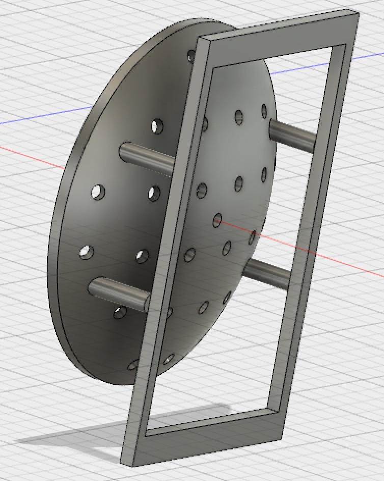
The modified perimeter with an extra frame to attach the perimeter to the headset via magnets.
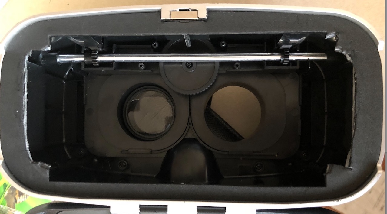
The VR headset that was gutted in order to fit the perimeter. Magnets would be placed along the edges and secured to the frame of the perimeter.
However, Sophie and Anna ran into several problems with the new design. First, the previous perimeter was created so that the dome would be located 6.35 cm away from the eye. However, because of this close proximity, some of the LEDs at the edges of the dome would be obscured by the eyepieces. Thus, the desired 30° visual field could not be measured with the current design.
This problem could be solved by increasing the distance the perimeter is set from the eye. This solution presents additional problems because the dome would then have to increase in size and thus, not fit within the casing of the VR headset. Sophie and Anna are currently discussing with their mentor the best way to overcome this problem. Another solution to this problem is to completely remove the eyepieces. However, in the final design that Halma produces, the eyepieces have to be added back on in order to adjust for the patient’s eyesight. This problem can then be addressed when Halma designs the final VR headset model.
Judy and Khairah are currently building a circuit utilizing two LED drivers and multiple single-color (blue and red) LEDs, in order to further understand its implementation using RGB LEDs. Using Arduino, we have created a code that executes the blinking command in all the 24 LEDs. This will then be modified appropriately when we replace the single-color LEDs with RGB LEDs. So far, we realized that the usage of many LED drivers and LEDs will definitely take up a lot of space within the device, and we are researching ways to minimize space usage while ensuring that they are still cost-effective.
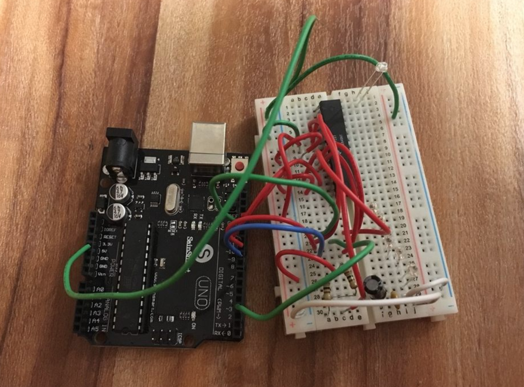
Building the circuit – still in progress.
Since our device is meant to be portable and utilizes batteries as its main power source, we decided that it is important to incorporate a mechanism that indicates that the battery power has reached a certain threshold–therefore prompting the user to replace the batteries as needed. We are also researching ways to incorporate this into our code.