April 13, 2018
Posted by wordae on Sunday, April 15, 2018 in Uncategorized.
This week, Judy, Khairah, and Sophie are continuing to solder the complete circuit onto regular PCB boards. Their current iteration of the circuit has 20 clear RGB LEDs and 4 LED drivers. They have tested the circuit using an Arduino UNO, and a laptop as the power source and have proved that it is functional. They also soldered an Arduino Nano to the board. This will save space compared to the Arduino Uno. They are also planning to replace the clear RGB LEDs with diffuse RGB LEDs, which is more in line with the specifications of Halma’s original prototype. Additionally, they are also working with Anna to determine ways to integrate the intended power source and the battery monitoring circuit, with the blinking LED circuit.
The LTC 4150 coulomb counter has arrived, and Anna will wire and implement the code for the battery monitoring circuit over the weekend.
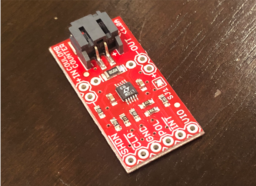
The LTC 4150 coulomb counter will help us calculate the percentage of battery remaining, which can then be converted into a green, yellow, or red light from an RGB LED. This will allow users to quickly assess battery life.
Because the circuit is too large to fit in the headset as is and the wires are too stiff to move the dome independently from the rest of the circuit, Sophie and Anna have devised a new way to switch the dome between the right and left eyes and have extended the headset. The headset now includes a longer body that can accommodate the circuit.
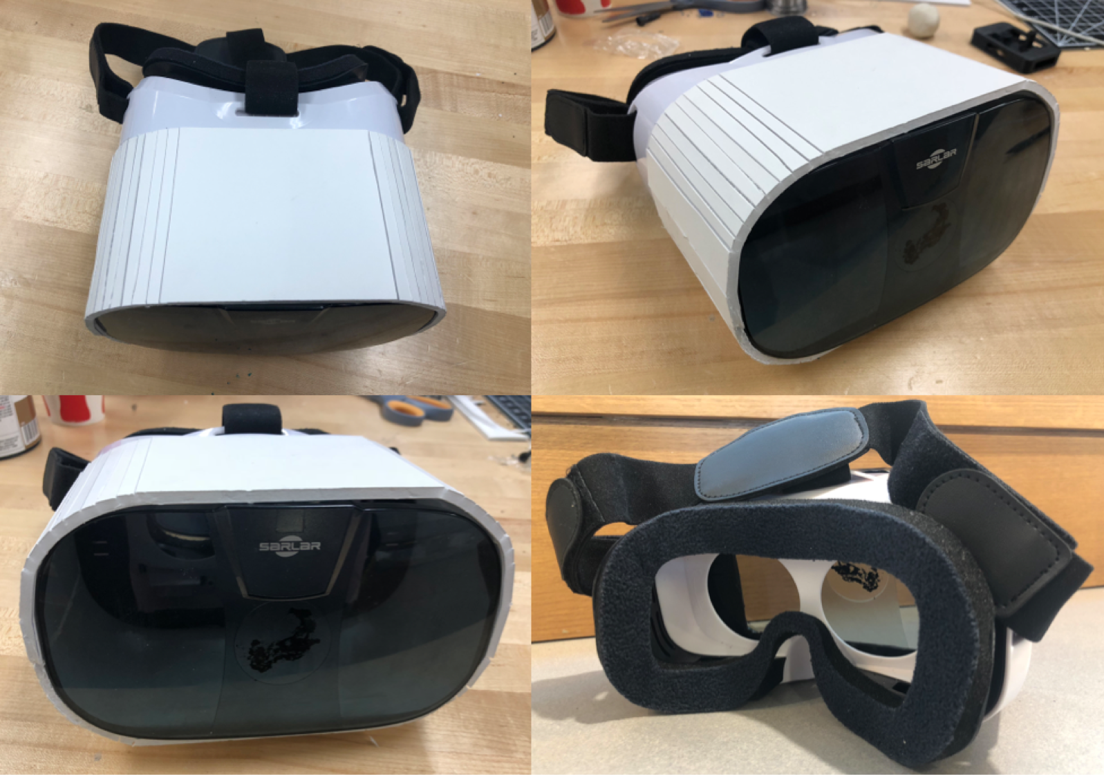
The new headset design. This prototype’s walls are made of foam board. future iterations will be entirely hard plastic.
This component can be separated from the part of the headset that attaches from the patient’s head. This allows the technician to remove the entire circuit and dome simultaneously and flip everything upside down, thereby switching the dome to the other eye. Because the dome is symmetric, this does not affect the test.
Sophie and Anna have also updated and printed battery casing what will house the battery, on switch, and battery indicator light. They will find a pin to make the door operational and plan to hold the door closed with magnets. This casing will be attached to the outside of the headset with screws.
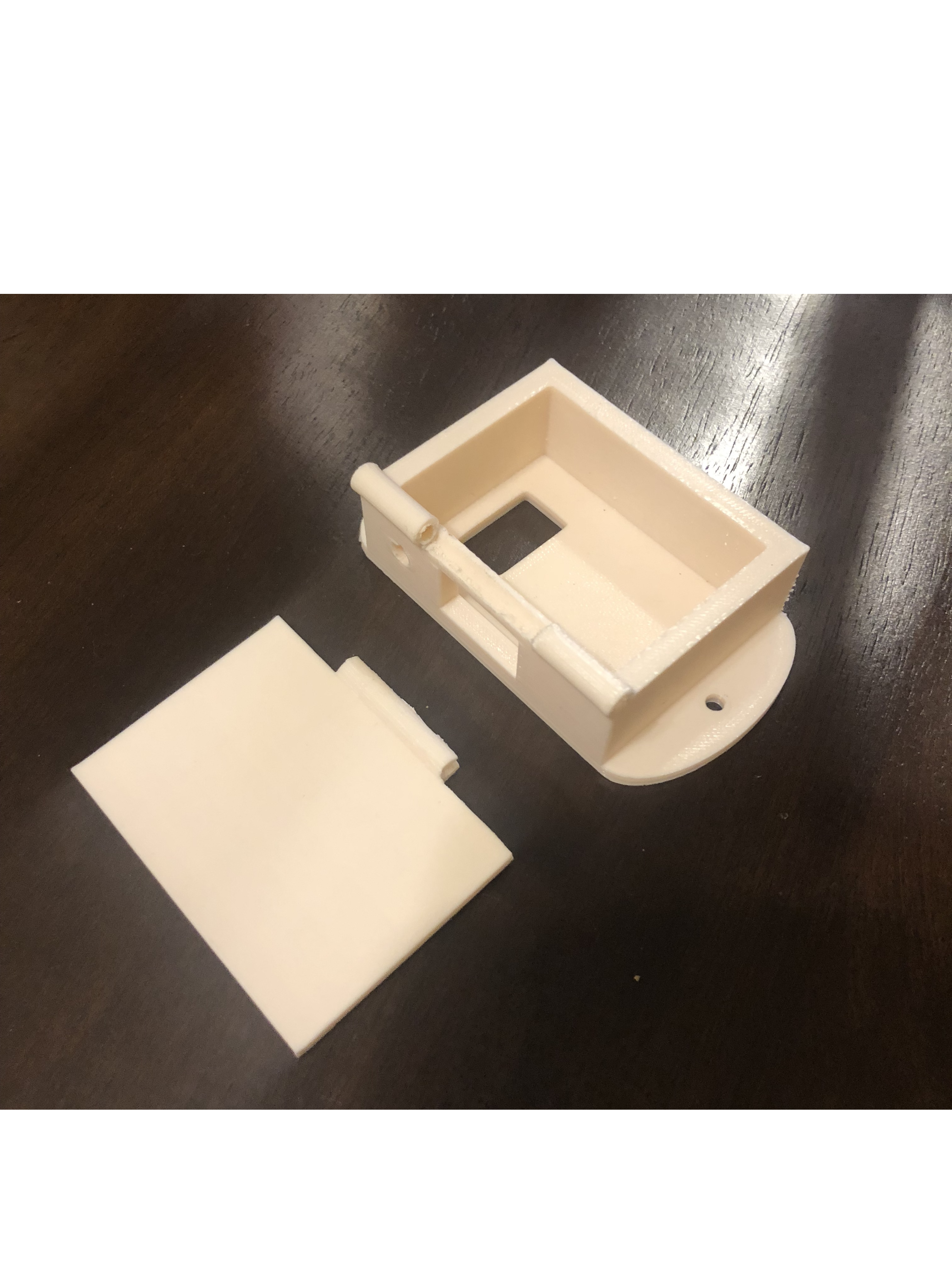
3D-printed battery casing. This casing contains two holes in what will be the top side, one rectangular, one circular, that will accommodate the on/off switch and the battery indicator LED respectively. The hole in the back will allow wires to be fed from the battery, LED, and switch to the rest of the circuit housed inside the headset.
The poster has also been updated.