March 30, 2018
Posted by wordae on Friday, March 30, 2018 in Uncategorized.
The housing team has finished their prototyping and will make final adjustments to their CAD designs if needed. Sophie and Anna have begun work on a battery casing for our 9V battery and will continue to do so this week.
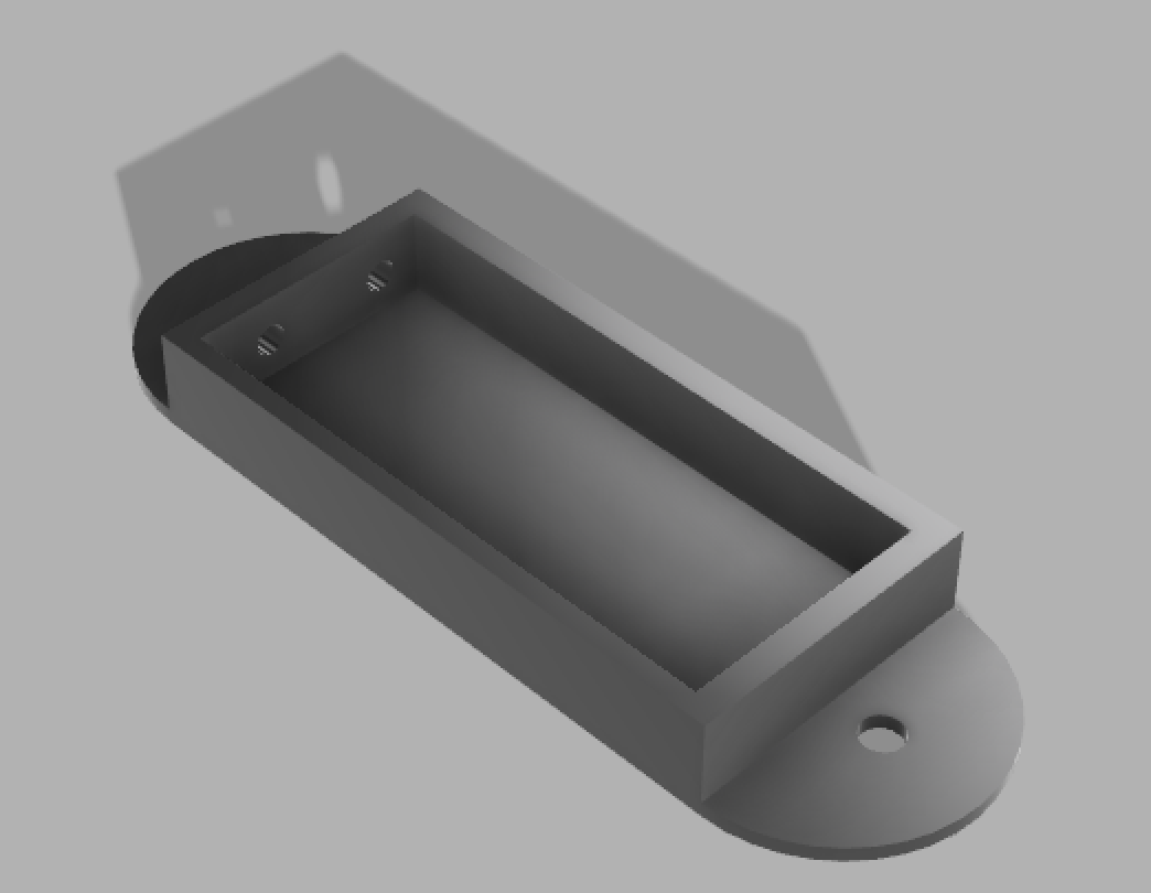
Battery casing version 1. This casing will be attached to the outside of the headset and will hold the battery and monitoring circuit. Future iterations will include a door on the front to provide protection for and access to the battery.
Sophie and Anna have also been helping the electronics team on their projects as the housing projects come to a close and Design Day grows closer. Anna has been working with Lumasil’s Shashank Manjunath and Tony Russo so that she can begin developing a battery indicator. The battery indicator will be mounted on the headset’s outside casing along with the battery and will ensure that the user knows when the battery is low. Shashank is helping her develop a monitoring algorithm, and Tony explained the battery testing process using the EE design lab’s ELVIS boards. Anna has obtained access to the EE design lab through Dr. Holman and will begin testing this weekend.
Khairah and Sophie started working on soldering part of the complete circuit on the flexible PCBs. For now, they have constructed a circuit with one LED driver and 5 LEDs. From there, they could approximate the space needed to mount the complete circuit within the headset. However, they are experiencing problems with the circuit being non-functional, despite it working on a regular breadboard. They will use a multimeter to test for continuity in order to ensure that the circuit has been soldered properly. Additionally, they are thinking of moving to regular PCB boards in order to decrease difficulties associated with soldering the components. After the entire circuit is soldered, Khairah and Sophie will mount the circuit, including the battery, to the dome and headset. They will mount the battery and the switch on the outside casing of the headset for easy access and to ensure that as much space as possible is reserved for the LED blinking circuit itself.
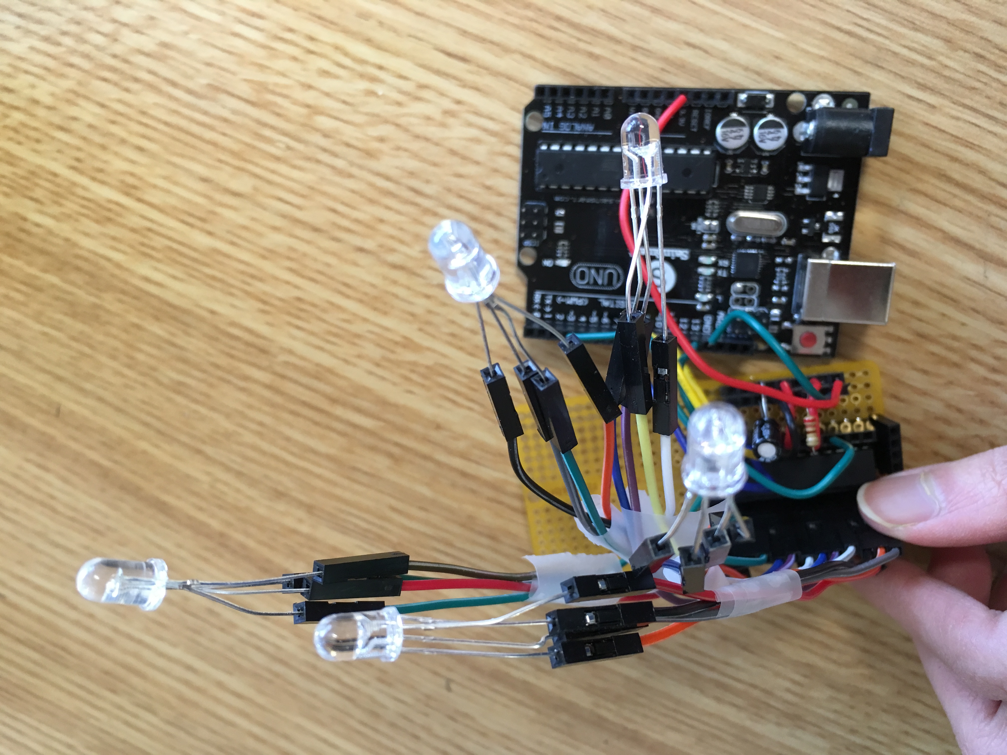
Soldered circuit. This is our first attempt to implement our circuit on flexible PCBs. This circuit is currently non-functional but will be improved throughout next week.
This week, Judy expanded the external breadboard circuit to include 25 RGB LEDs and 5 LED drivers, which demonstrates that our circuit design for connecting 24 LEDs for the flashing blue and red lights and 1 LED for the white fixation light was effective. In the previous iteration of the circuit design which used two LED drivers with 10 LEDs, a 3.3 V power source was used. Judy found this week that using 3.3 V power source caused improper flashing of the LEDs, so that a 5 V power source was necessary to power the 5 LED drivers. Capacitor and resistor values were also adjusted to accommodate the increased number of LEDs and LED drivers. Finally, Judy altered the Arduino code for the blinking mechanism to streamline and shorten the length of the code. This coming week, Judy will make a PCB design so that she can order a custom PCB for our device.