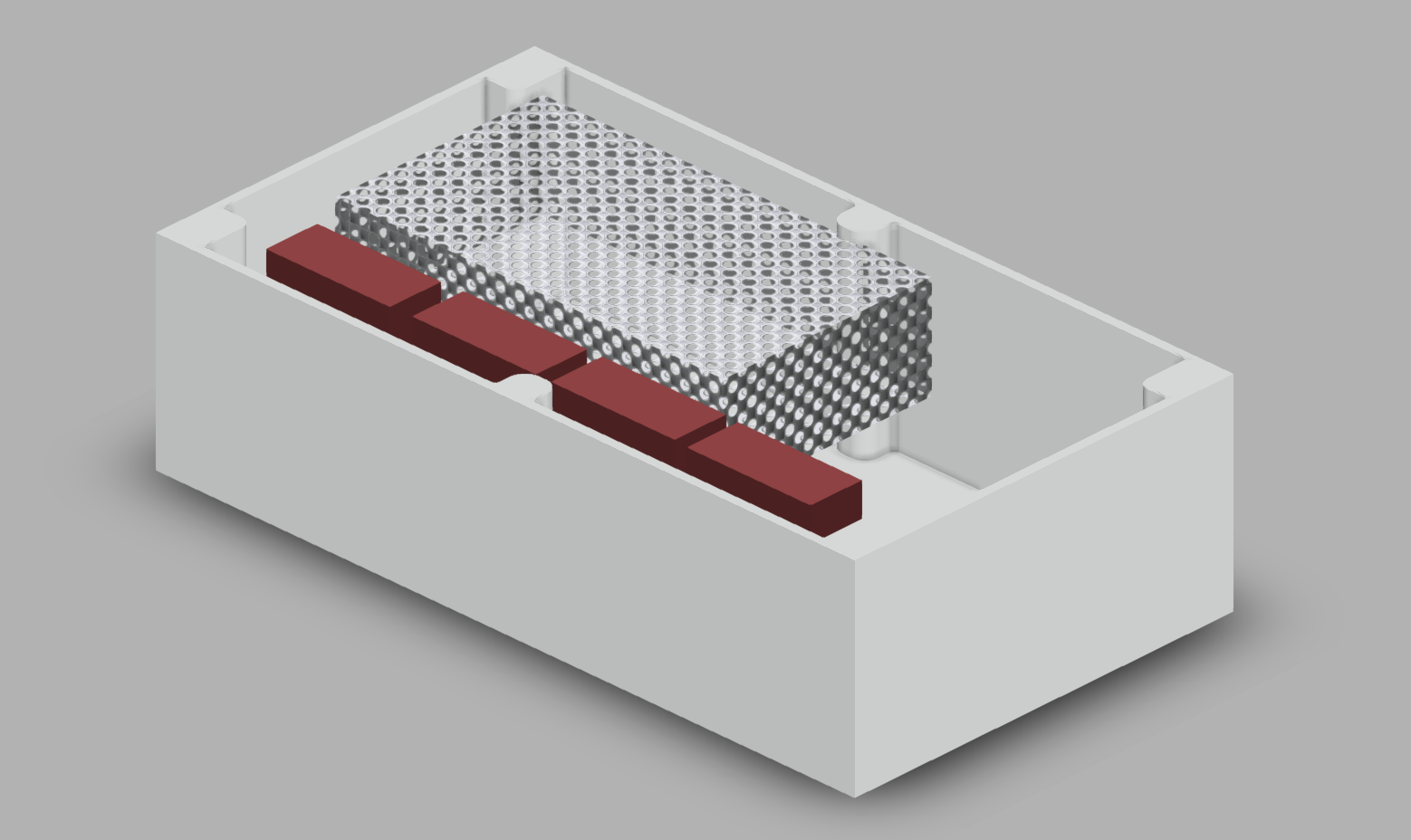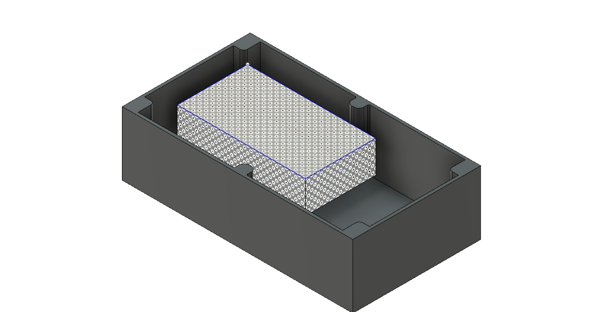
Figure 1: CAD model for the outer box (top removed for visibility) and the power source inside. Components to add: central driver housing and support shelf, water cooling system, and arduinos.
CAD was used to model the outer box of the pump system. The outer box is a watertight container with a port to connect the motors to the electronics inside and supply power to the drivers and arduinos.
The ultimate goal of the CAD design is to model each of the components in our project and fit them together within the outer box.The box will be a tight fit for the entire set of electronics needed to run the peristaltic pumps autonomously, but should contain everything and keep them sealed from the rest of the bioreactor.

Figure 2: Driver housing from previous version. The housing and a structural central driver housing will improve on many aspects of the design.
Additional planning was conducted for the central driver housing for the EZ drivers. The EZ drivers must be water cooled, and the width of the tubes, size of their pump, and size of the cooling system must all be taken into account. Additionally, it is unclear how many chips one pump and one set of tubes can cool. The group has come up with a design that maximizes the surface area between the tubes and the drivers. If one can handle all of the EZ drivers, then the system will fit snugly in our current iteration of the driver housing and can still be placed underneath the power source. If it requires more space, the modular driver housing can be arrayed in an 1×4 configuration and placed vertically against the side wall.
The team is waiting to receive CAD files of the central driver housing as it exists in the previous version, so that we may edit them to account for the additional drivers and water cooling system, as well as improvements to wire organization, modularity, repairability, strength, and ergonomics. Additionally, we are waiting on design specifications for the water cooling system, so that the next iteration of the housing can account for them.