Over the past week we have progressed on and/or finished the following six tasks:
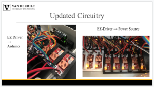
- Wires Reconfigured and Reorganized
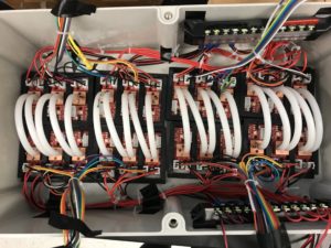
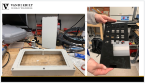
Figure 1: Organization of heat sink tubing (center) and wire (pushed to the sides of the box)
There are a variety of wires, tubing, and other electronic connections that are assembled in the box. In order to keep better track of each component and all of the connections, the wires coming and going to each EZ driver were grouped together and zip tied together. They were then moved to the outer edges of the box to leave room for the water cooling tubing along the center of the box. The water cooling tubing had to stay in place so that they could be connected to the heat sinks. Lastly, the power relay stations were adhered to the side of the box so that they would stay in place if the system was moved. By organizing the inside of the box this way, it is much simpler to keep track of all of the connections and components.
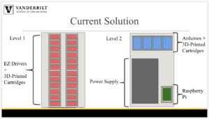
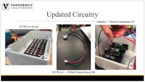
2. Water Cooling System – All Tubing Attached to the 24 EZ Drivers
The water cooling system is quickly coming together. There will be four parallel, identical systems working to cool our EZ drivers simultaneously. Having four systems instead of one will allow for much more cooling and decrease the likelihood of carrying residual heat from one EZ driver to the next. Every set of 6 EZ drivers will be cooled by one of these systems. All the tubing has been attached to the EZ drivers (see Figure 2).
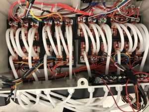
Figure 2. All tubing connected to the EZ Drivers for hermetically sealed water cooling
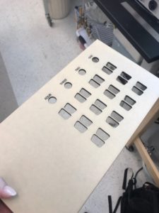
Additionally, there needed to be 4 inlet holes and 4 outlet holes in the box to bring the water in and out, so all 8 holes were drilled and prepped with their respective tubes through a plug for hermetic sealing (Figure 3).
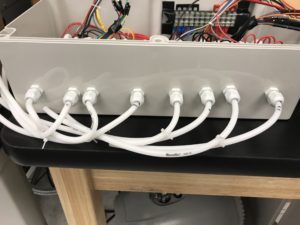
Figure 3. Inlet and outlet holes for the water cooling system with the tubes hermetically sealed
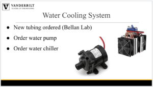
Lastly, our radiators have arrived, so we hope to have the water cooling system completely assembled by next week and running efficiently.
3. Updated CAD Modeling
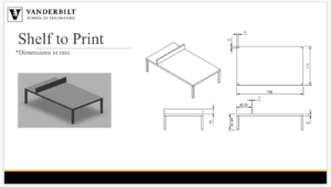
After attaching the tubing for water cooling, we determined that our shelves for the Arduinos and power supply would not be high enough in their original iteration. Therefore, we measured out the height from the bottom of the box to the top of the tubing and readjusted the heights of the shelves to accommodate the tubing.  Figure 4. The shelf that will hold all four Arduinos and is high enough to fit the water-cooling tubing below
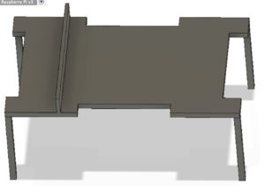 Figure 5. The shelf that will hold the AC/DC power converter, as well as a slot for the Raspberry Pi is now high enough to accommodate the water-cooling tubing below
4. Motors began to be prepped for connection
This week, we obtained 15 of our 24 motors that will be used by the Bellan lab for running parallel perfusion experiments. In order to make these stepper motors compatible with our system, the four wires that extended from the motor needed to be prepped for connecting to our hermetically sealed box. This was done by soldering on D-sub bulkhead connectors to the 15 motors that we currently have.
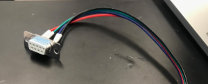 Figure 6. The D-sub bulkhead connector allows for the wires from the motor to be connected to the hermetically sealed box.
5. Arduino Connections
Additionally, the four Arduinos were powered and connected to the Raspberry Pi via USB cable. We are considering working with a Bluetooth or WiFi connection, but are currently proceeding with a wired connection due to its ease of use.
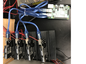
Figure 7. The four Arduino Unos are connected to our Raspberry Pi via four USB cables
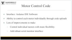
6. Code Writing
A github respository has been created to organize the code for both the Arduinos and the Raspberry Pi. The Arduino code enables control of the lower level motor functionality for each of the 6 stepper motors it is connected to. The Raspberry Pi code is written in Python and communicates with the Arduino through the pyserial library. Wireless Virtual Machine control is enabled through a viewing software.