


Senior Design Project Report – January 24, 2019
Reply


Senior Design 2018-2019 Project Plan:
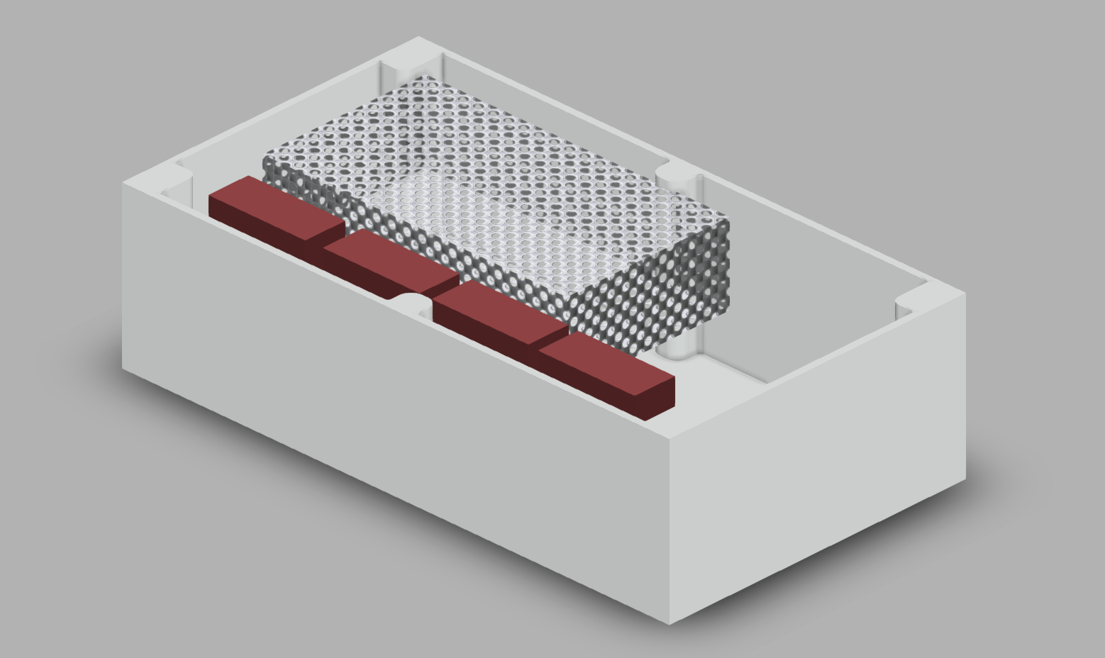
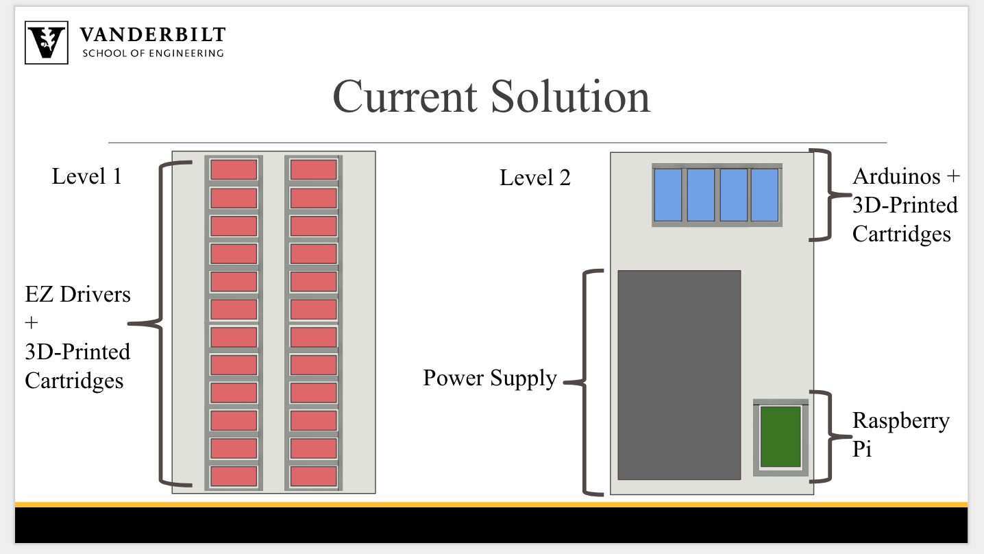
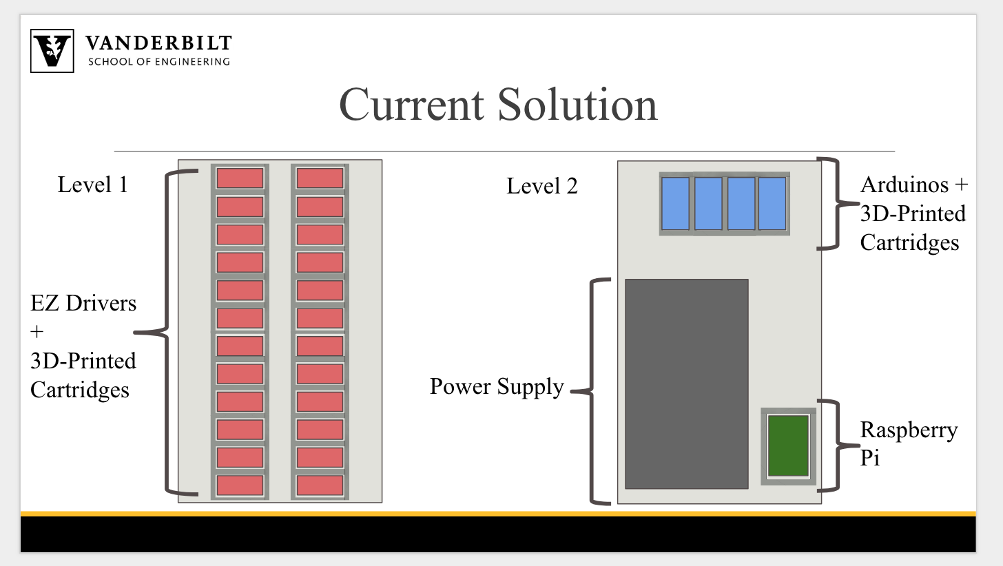
Figure 1. CAD Drawing of Central Housing Design with EZ Driver Containers (Red Boxes) and Power Supply (Grated Box)
The previous CAD model (see Central Drive Housing Design – Part 2) has been expanded upon in this update (Figure 1). The 3D-printed containment for the EZ drivers is currently capable of holding six of the drivers. In total, we need 24 EZ drivers so four of the EZ driver housing components are shown in red above.
The placement of the EZ drivers is currently being optimized. Figure 1 shows one of the potential locations for them. They may also be placed horizontally underneath the power supply, creating two levels in the central housing. The optimization of the location will primarily depend on three factors: total amount of usable space used, wiring and tubing configurations, and ease of placing/replacing the components.
We will soon be adding in placeholders for four Arduino boards and a Raspberry Pi within this CAD sketch. We will also soon be including more accurate representations of the EZ driver housing components with the aid of Brian O’Grady from the Bellan Lab. Additionally, we are waiting on design specifications for the water cooling system, so that the next iteration of the housing can account for them. This will also aid in our choice of where to place the EZ drivers. It is possible that the water-cooling system will constrain our design much more than is currently being accounted for.
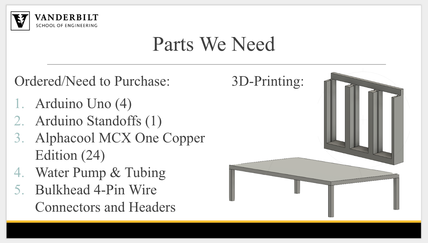
In the meantime, we are compiling a list of necessary materials and the corresponding prices in order to budget accordingly. We have a list of materials that we currently have available in the lab, and another list of what we need access to or to purchase. The list includes all of the physical components necessary, as well as any CAD sketches or instruction details. Since one of the main goals for this project was to create an affordable system, we are also currently researching low-cost materials and exploring what components can be 3D printed.
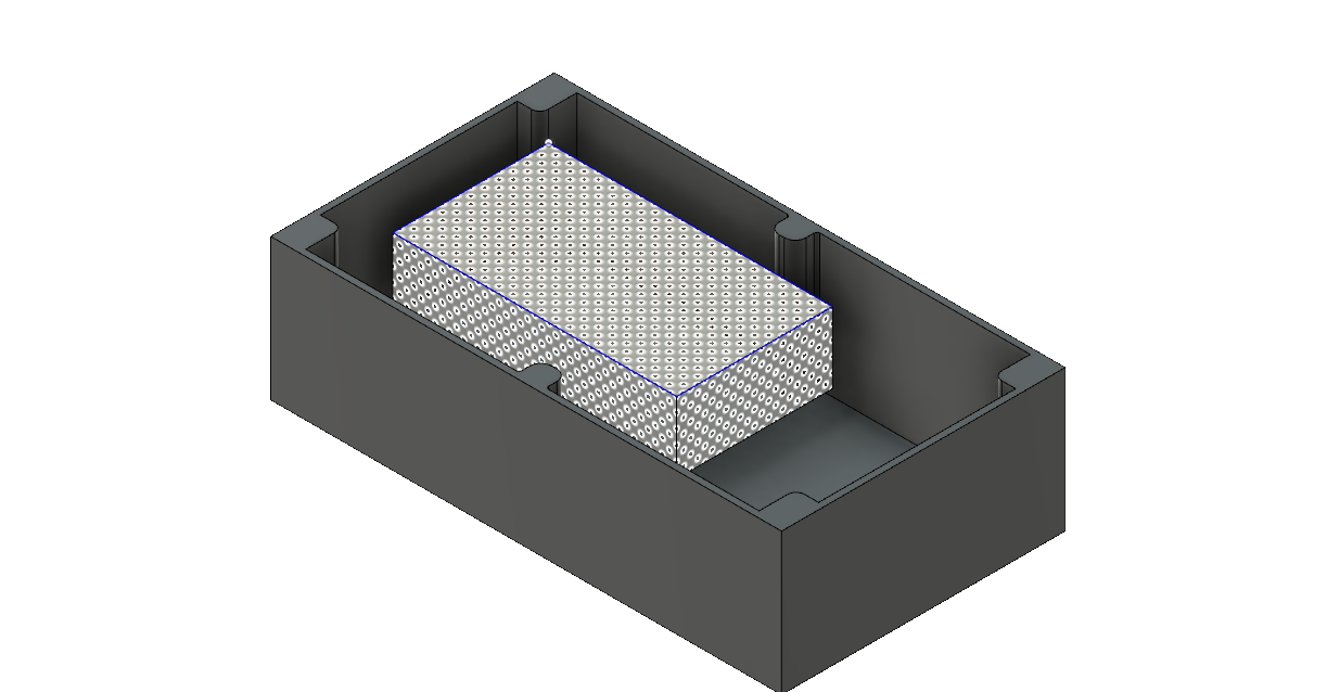
Figure 1: CAD model for the outer box (top removed for visibility) and the power source inside. Components to add: central driver housing and support shelf, water cooling system, and arduinos.
CAD was used to model the outer box of the pump system. The outer box is a watertight container with a port to connect the motors to the electronics inside and supply power to the drivers and arduinos.
The ultimate goal of the CAD design is to model each of the components in our project and fit them together within the outer box.The box will be a tight fit for the entire set of electronics needed to run the peristaltic pumps autonomously, but should contain everything and keep them sealed from the rest of the bioreactor.

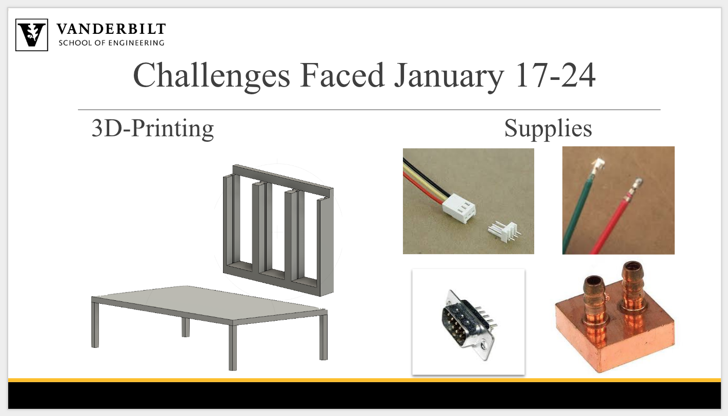
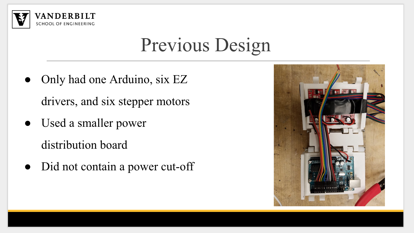
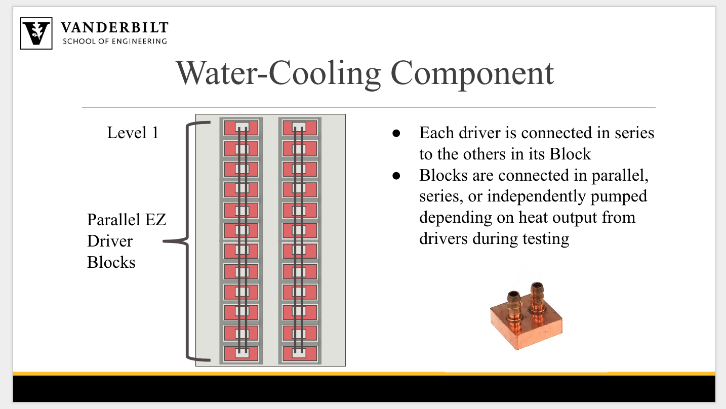
Figure 2: Driver housing from previous version. The housing and a structural central driver housing will improve on many aspects of the design.
Additional planning was conducted for the central driver housing for the EZ drivers. The EZ drivers must be water cooled, and the width of the tubes, size of their pump, and size of the cooling system must all be taken into account. Additionally, it is unclear how many chips one pump and one set of tubes can cool. The group has come up with a design that maximizes the surface area between the tubes and the drivers. If one can handle all of the EZ drivers, then the system will fit snugly in our current iteration of the driver housing and can still be placed underneath the power source. If it requires more space, the modular driver housing can be arrayed in an 1×4 configuration and placed vertically against the side wall.
The team is waiting to receive CAD files of the central driver housing as it exists in the previous version, so that we may edit them to account for the additional drivers and water cooling system, as well as improvements to wire organization, modularity, repairability, strength, and ergonomics. Additionally, we are waiting on design specifications for the water cooling system, so that the next iteration of the housing can account for them.
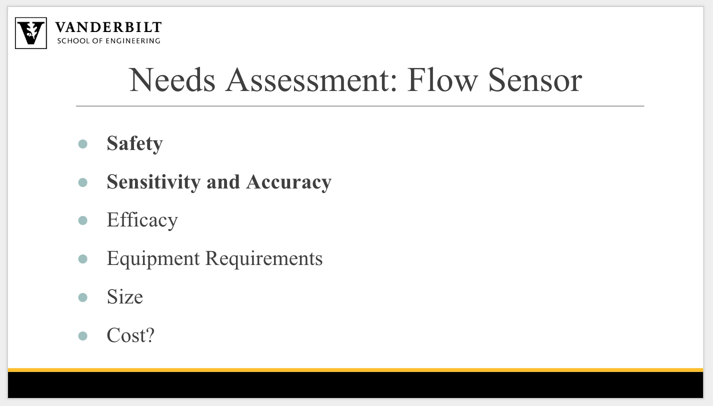
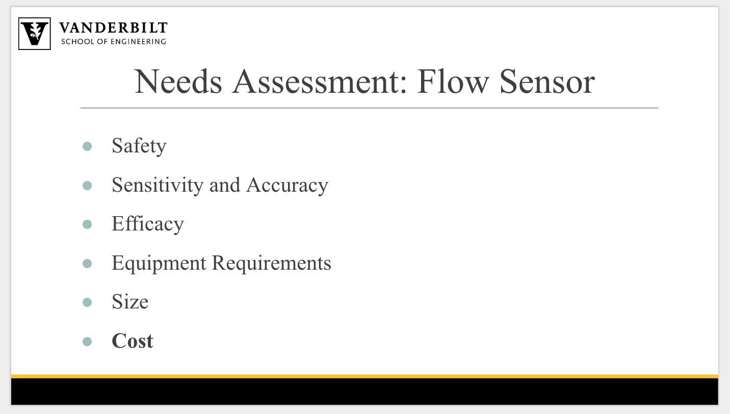
To begin, a preliminary Needs Assessment was delineated:
Needs Assessment:
Design Quality
Next, the layout of the housing box was precisely measured for creation via 3D modeling. This modeling is still in the works.
Then, brainstorming began on how the inside of the box would take shape. Given the space, there will be two levels. The top level will be the power supply that is supported via a 3D-printed shelf. The level underneath this power supply will house the EZ Drivers, which send information to the pumps and are controlled via Arduinos. The leftover space will house the Arduinos and the Raspberry Pie controller (this controls all the Arduinos).
All supports and casings for the equipment will be 3D-printed.
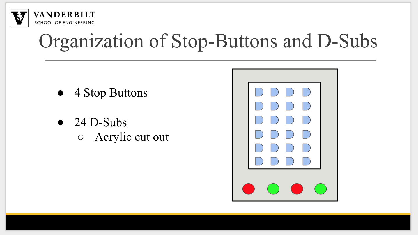
We are in the process of brainstorming the best way to organize the wires within the housing box. We need a 3D-printer EZ Driver structure to:
The next step will be redesigning the Central Driver Housing, specifically creating: