Our final design needs to utilize existing commercial parts as much as possible. We decided to order and evaluate a Sturmey Archer 3-Speed Internal AW Hub in order to better understand how a gear hub functions. After taking apart and examining the hub, we plan to evaluate the feasibility of modifying the hub to reverse the first and third gears.
First, we connected the 3-speed shifter and cable to the clutch. We observed the mechanism of the clutch response to movement of the shifter. Next we tested each gear ratio by spinning the power input for one full rotation and observing the rotation of the output. This was to verify that the hub functioned properly before we began the process of reverse engineering.
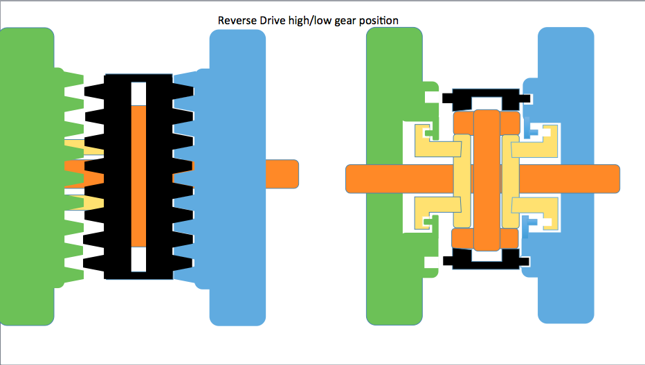
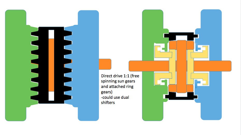
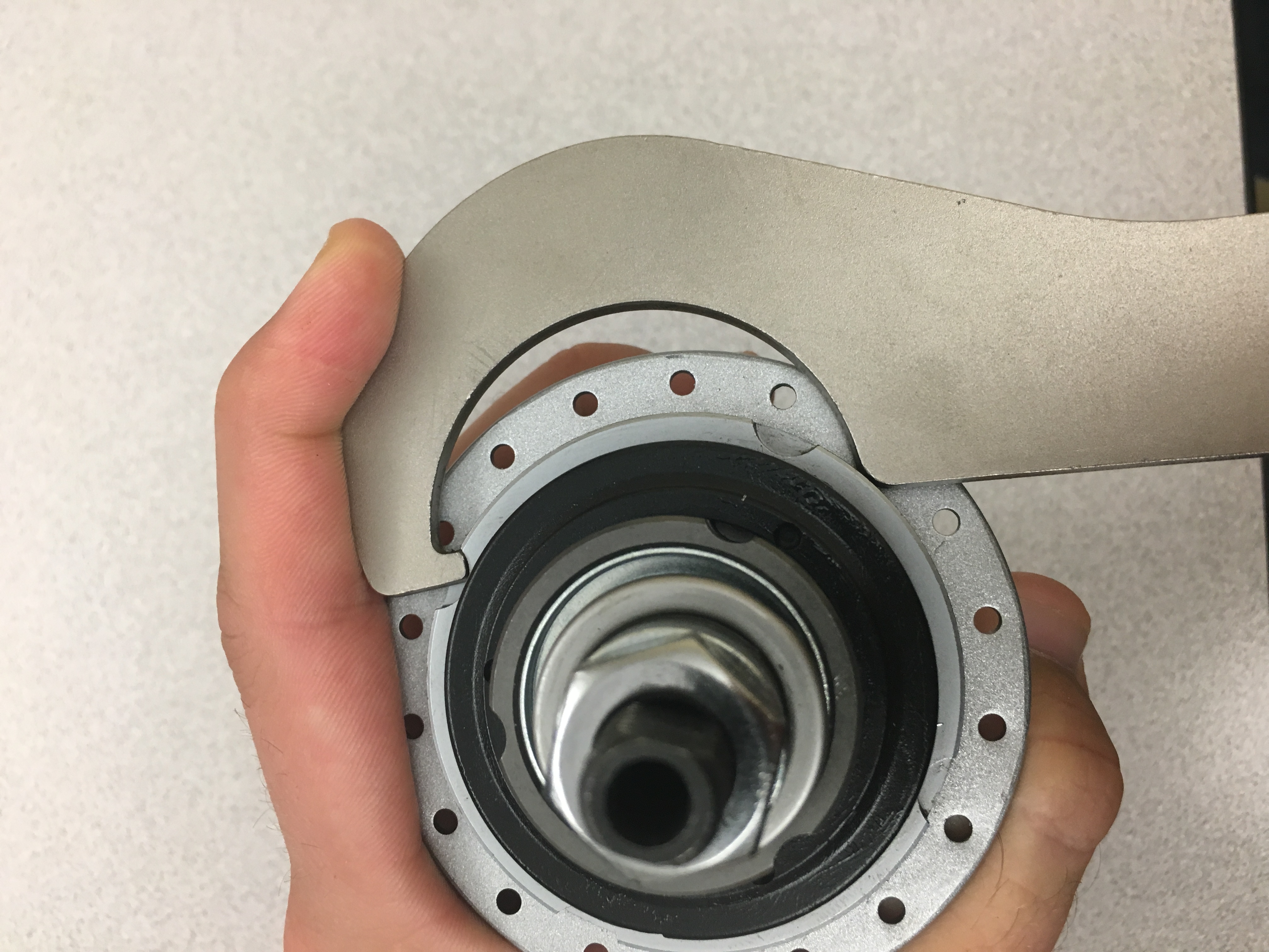
Next we utilized the instruction manuals and online forums to take the hub apart. We removed the main shaft from the outer hub shell. The Sturmey-Archer hub utilizes a planetary gear concept. The ring gear and planetary gears are located within the hub, while the hub itself functions as the power output. The sun gear is attached to the main shaft that also functions to move the clutch. We were able to remove the main shaft and observed the mechanism of the clutch and driver. As the shaft is in the low gear, the position of the clutch keeps the prongs of the ring gear retracted so that it does not engage the outer shell. The driver powers the ring to produce a 1:3 low gear ratio. The shaft is then moved laterally to the 2nd gear “middle” position. The clutch shifts so that the prongs of the ring gear move outwards and engage the outer shell. The driver still powers the ring gear in this position, which in turn powers the outer shell at a 1:1 ratio. In third gear, the divots at the end of the clutch engage the knobs on the back wall which are attached to the planet carrier. This allows the driver to power the planet carrier with the ring gear still attached to the outer shell which results in a 3:1 high gear ratio.
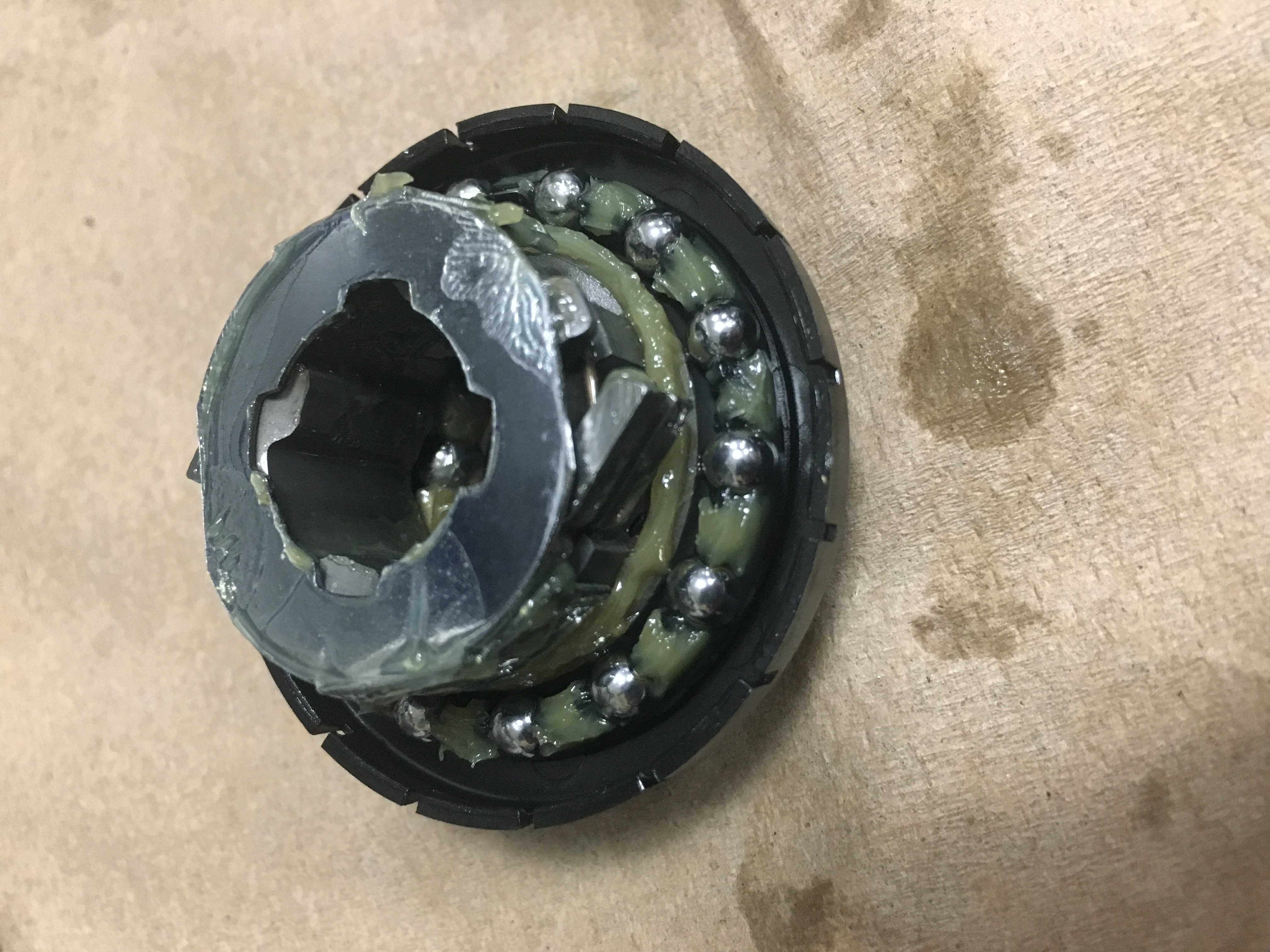
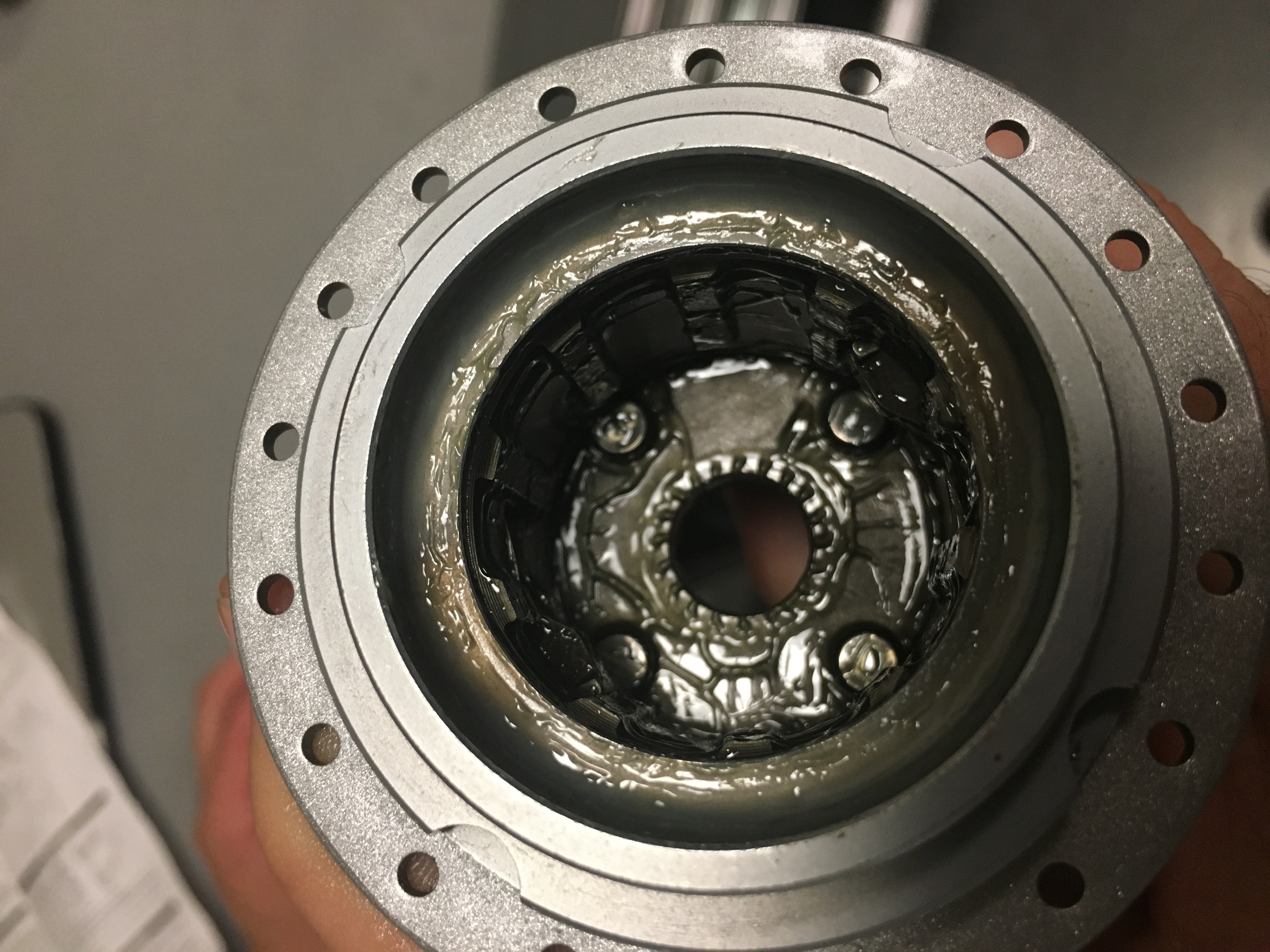 One challenge we are facing is whether it is possible to completely disassemble the hub to give us complete access to the gear systems. As of now we have only been able to take out the sun gear, clutch, and driver. We have not been able to remove the planet gear carrier from the external hub. Sturmey-Archer recently re-designed their hub and made it slightly more complicated and difficult to disassemble. We are working to address this difficulty.