Project Update 03-30-2018

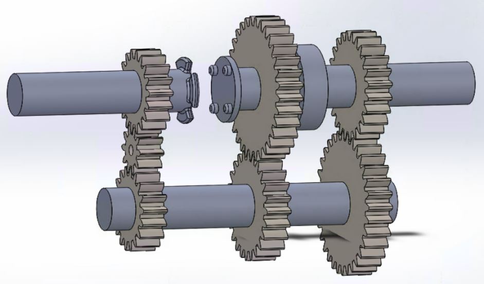
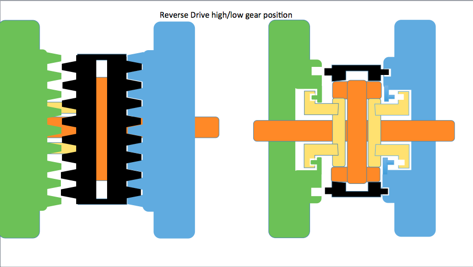
This week we have made our first physical prototype of our gear hub. Our parts were delivered on Tuesday of this week. We created a full catalogue of parts from AndyMark, a company that makes gears primarily for use in robotics competitions. Here is the mock up we have so far.

Screenshot_2018-03-30 14.09.31_AnXqq5


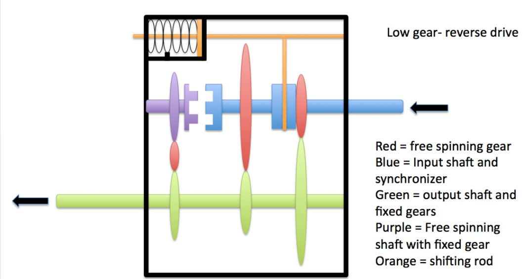
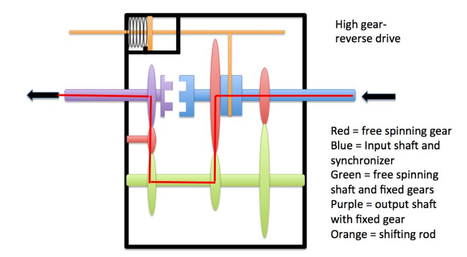
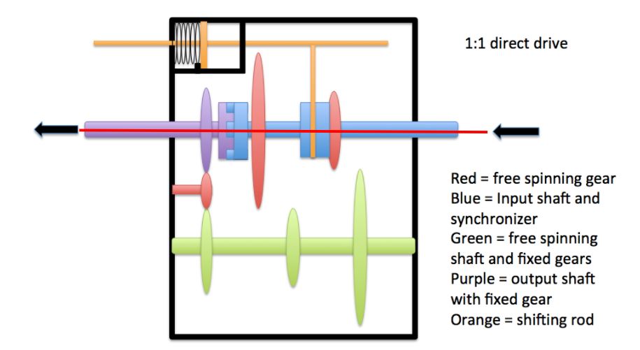
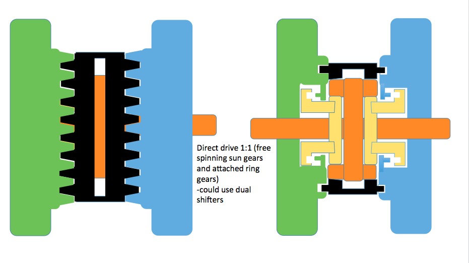
This current prototype can show the demonstration of the hub for reverse low and high gear set ups depending on the position of the dog gear as shown in the image above. For us to demonstrate direct drive, we will need to go to the machine shop to split the top(input/output) axle into two separate components. This way we can slide the axle along its axis and the current sets of gears on the right side will no longer be connected.

We have ordered the required parts needed to do this and set up a consultation at the machine shop to do just this.

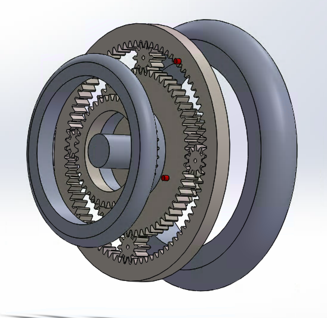
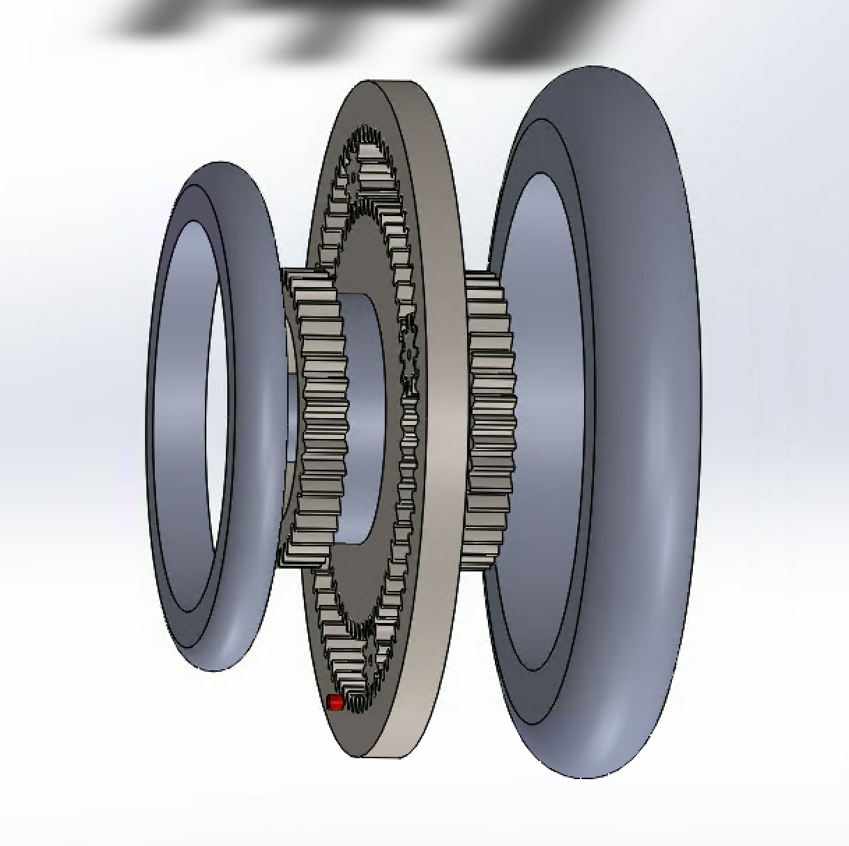
We are also considering how we are going to demonstrate the function of this hub on design day. We have acquired a bicycle wheel and are planning to send the half-inch hex axle through the wheel and have a handle on the other side to do a demonstration. A solid works mockup of this is shown below.

Screenshot_2018-03-30 14.12.55_0kuVTl

The output(left side) of the hub is a half inch hex axle. This will interface directly with the bicycle wheel. The hand rim is shown on the right side. This will all need to be encased in an aluminum hub to maintain structural integrity.

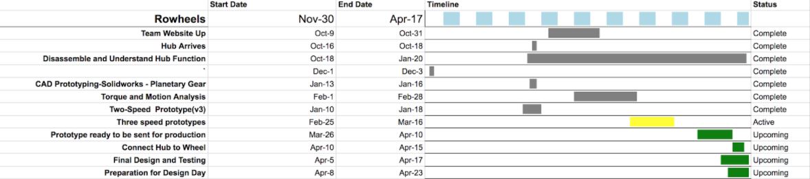
Shown below is where we are in the timeline for this semester.

Screenshot_2018-03-27 20.51.45_W315NF

Project Update 03-16-2018

After meeting with the mechanical engineering professor, we developed a multi-axle gear hub that is similar to a manual automotive transmission. This design, shown below in the low gear reverse drive, utilizes three axles and allows for low and high gear reverse drive and for 1:1 direct drive. We showed this to our Rowheels sponsor and his main concern was that this is a non-concentric design, as our power input (blue) and output (green) were in different planes. gear1

To address our sponsors concern, we simply redesigned this gear box to move the power output to the purple axle, giving us a concentric design. We can shift between the two reverse gears by pulling the orange shifting rod via a cable which then slides the blue synchronizer along the blue input shaft and allows it to mesh with either gear ratio. gear2

To shift into direct drive, the blue input shaft is slid into connection with the purple output shaft via a second shifting mechanism. Having these separate shifting mechanisms is a safety precaution for the user, as shifting from reverse to forward drive while in motion could jam the gears and jerk the user forward. gear11

Here is our preliminary SolidWorks design of this multi-axle gear hub and Gantt chart. We believe this hub can be manufactured with off the shelf components, such as the ICP dog clutch shown below and we are in the process of getting these pieces to create a working three-speed prototype. solidworks gear11gannt dog clutch

Project Update 02-23-18

This week we met with a professor in the mechanical engineering department and asked him to review our gear hub design. Upon first look, he commented that our design was reminiscent of a manual automotive transmission. Automotive transmissions use a piece called a synchronizer (pictured below) to slide back and forth along an axle and engage different gears. Our design utilizes a similar concept. In our most recent prototype we decided to use 4 knob protrusions instead of the many teeth shown on the synchronizer. We learned this week that the teeth would actually be just as durable as the knobs, and would make the shifting much smoother. Screen Shot 2018-02-23 at 2.46.56 PM

Our meeting also opened our minds to the possibility of utilizing automotive components in our design. These components are much more common and available than bike parts. In the upcoming week, we are going to evaluate the feasibility of using a dual shaft gear box, similar to a manual car transmission. Our goal in doing this is to reduce the cost of our hub by reducing the number of custom components. Meanwhile, we are continuing to search for and contact potential manufacturers.

Project Update 2/9/18

In our previous oral report, we discussed the modification of the clutch/gear system to use clutch plates that engage laterally along the face of the gears instead of vertically. We have been woking to incorporate this design into our SolidWorks prototype and run a quantitative torque analysis.

In the meantime we have also begun brainstorming for our next prototype: the 3 gear system that adds a direct 1:1 drive. Our current plan is to use the same prototype as our 2 gear system but to add in a lever that moves the entire input hub closer to the output. This forces both the input hub and the output hub into connection via the ring gear and allows the sun and planetary gears to spin freely. The hub could then be moved back into the reverse drive position and the user will be able to shift between high and low gears as previously explained.

Screen Shot 2018-02-10 at 2.47.02 PM

Screen Shot 2018-02-10 at 2.47.24 PM

Project Update 01-26-17

As referenced in our previous progress updates, we have been unable to access the Sturmey Archer hub directly. This was primarily due to it being a new version and the tools we had obtained being made for older versions of the sturmey archer. We contacted Sturmey archer and received information on the specific tool that would be required. A screenshot has been provided below. However, they also gave more specific instruction on how to destructively disassemble the hub. We will most probably proceed with the destructive route as we only need to understand its function.

Screenshot_2018-01-26 14.18.11_mnXkAJ

Alongside of this, we have begun to make progress regarding our Solidworks model. We have developed a more complex model of the planetary gear set. This model has both a high and low gear set up. However, there is no direct drive or a clutch system in place to shift between the two. We will continue adapting this to add these features.

Screen Shot 2018-01-26 at 4.15.27 PM Screen Shot 2018-01-26 at 4.14.50 PM Screen Shot 2018-01-26 at 4.14.23 PM

Project Update 12-01-17

We were able to borrow a tool from a local bike mechanic that we thought would be able to remove the inner piece (mentioned in previous update). However, upon attempting to use the tool, we found that it was sized for a slightly smaller hub (picture below). As a result, we were still unable to completely disassemble the hub. We are in the process of contacting more local shops in order to find the right tool for our hub.

IMG_4183


In the meantime, we have begun to model the hub using Creo Parametric 3D Modeling Software. Our hope is that by modeling the entire hub virtually, we will be able to virtually modify and test our designs without the need for heavy equipment and without damaging our current hub. Modeling the hub in Creo will be slow because we have to teach ourselves how to use the software along the way. However, we believe that this is an important investment of our time at this stage in the project.

image (1)

Project Update 11-10-17

Our final design needs to utilize existing commercial parts as much as possible. We decided to order and evaluate a Sturmey Archer 3-Speed Internal AW Hub in order to better understand how a gear hub functions. After taking apart and examining the hub, we plan to evaluate the feasibility of modifying the hub to reverse the first and third gears.

First, we connected the 3-speed shifter and cable to the clutch. We observed the mechanism of the clutch response to movement of the shifter. Next we tested each gear ratio by spinning the power input for one full rotation and observing the rotation of the output. This was to verify that the hub functioned properly before we began the process of reverse engineering.

Next we utilized the instruction manuals and online forums to take the hub apart. We removed the main shaft from the outer hub shell. The Sturmey-Archer hub utilizes a planetary gear concept. The ring gear and planetary gears are located within the hub, while the hub itself functions as the power output. The sun gear is attached to the main shaft that also functions to move the clutch. We were able to remove the main shaft and observed the mechanism of the clutch and driver. As the shaft is in the low gear, the position of the clutch keeps the prongs of the ring gear retracted so that it does not engage the outer shell. The driver powers the ring to produce a 1:3 low gear ratio. The shaft is then moved laterally to the 2nd gear “middle” position. The clutch shifts so that the prongs of the ring gear move outwards and engage the outer shell. The driver still powers the ring gear in this position, which in turn powers the outer shell at a 1:1 ratio. In third gear, the divots at the end of the clutch engage the knobs on the back wall which are attached to the planet carrier. This allows the driver to power the planet carrier with the ring gear still attached to the outer shell which results in a 3:1 high gear ratio.

IMG_3928IMG_3933
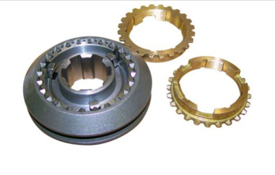
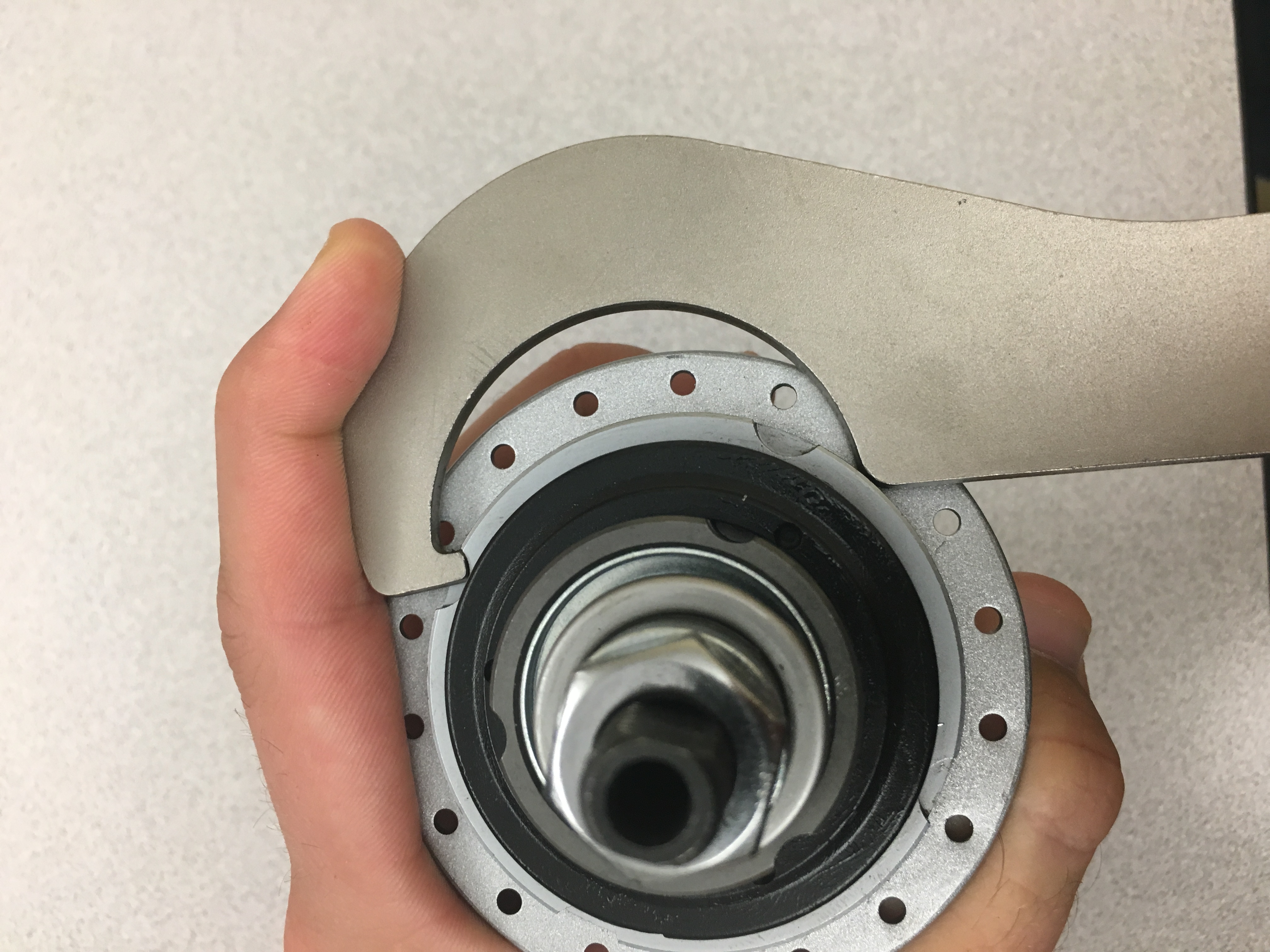
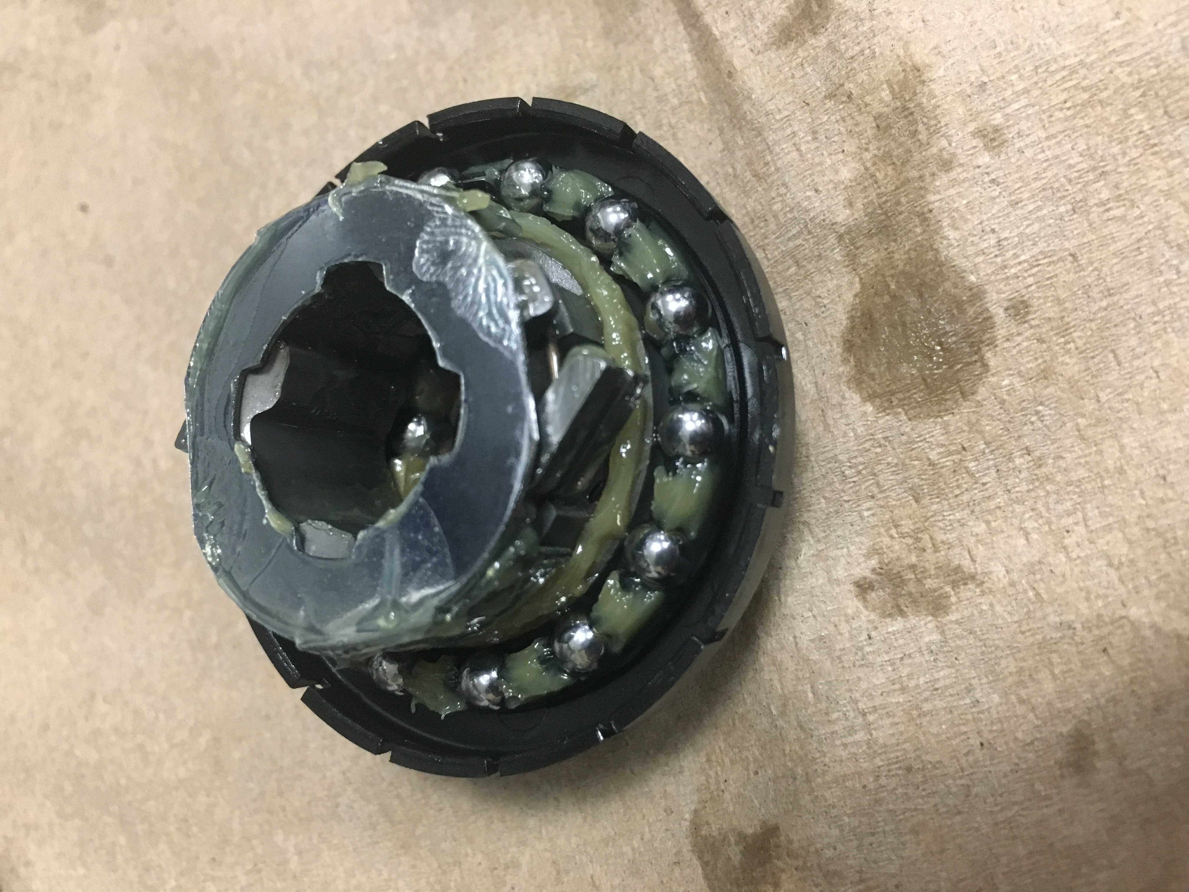
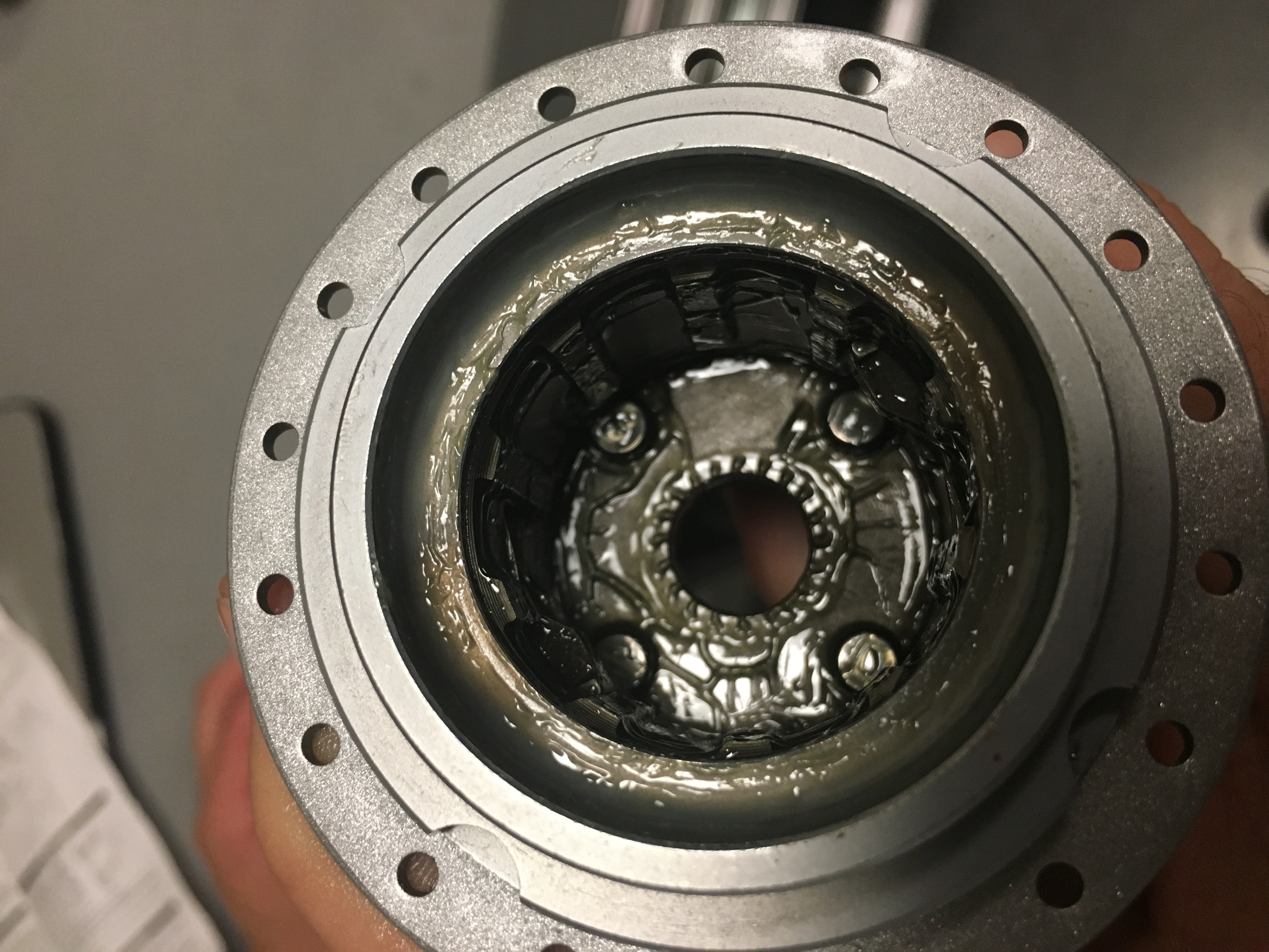
One challenge we are facing is whether it is possible to completely disassemble the hub to give us complete access to the gear systems. As of now we have only been able to take out the sun gear, clutch, and driver. We have not been able to remove the planet gear carrier from the external hub. Sturmey-Archer recently re-designed their hub and made it slightly more complicated and difficult to disassemble. We are working to address this difficulty.

Project 11-02-17

At this point in time, our team is nearing the end of brainstorming and beginning the prototyping phase. We have just obtained a physical sturmey archer and will be disassembling it to gain a better understanding of its function. We will focus our efforts in the immediate future of obtaining reversal of input and output shafts and in the long term, an effort to maintain a lightweight yet robust system. A brief timeline of our efforts so far is posted below.

10/30: Team Website Up

10/25: Submitted BME-ideas application

10/18: Sturmey Archer Hub arrived.

10/15: Patent search completed. Existing gear reversal patents were examined.