Powered on Passive Knee
Following extensive research on powered knee and ankle prostheses, we have begun pursuing an approach to using power in lower limb prostheses that we call “powered on passive.” This approach is based on the recognition that, for much of locomotion, biomimetic knee behavior is fundamentally passive (as described by Mochon and McMahon’s papers on ballistic walking circa 1980). In addition to providing highly biomimetic behavior, passive knees are fundamentally coordinated with the movements of the user, and typically give a user a much greater degree of agency over the actions of the prosthesis (relative to a fully powered prosthesis, which is able to generate its own movement independently of the user). Nonetheless, several activities require power generation at the knee, such as non-ballistic swing used in stair ascent and slow walking, and stumble recovery reflexes, in addition to stance-knee extension used during stair and steep slope ascent. In recognition of the value of retaining passive behaviors, in addition to the value of supplemental powered behaviors, we started developing powered on passive knees, which are capable of providing MPK-like strictly passive behaviors, but can also switch into powered behaviors in the instances users can benefit from power.
Because the passive knee behaviors require much lower output impedance than exhibited by powered devices, developing a device that can provide both passive ballistic and powered behaviors within the same stride is quite challenging. In order to provide the span of required behaviors, we developed a knee called the “ECT knee,” which employs an electronically-controlled transmission to switch a powered prosthesis between a high gear and low gear “on the fly” (in a few millisec); doing so enables the device to span the range of impedances, torques, and speeds require to provide a range of passive and powered prosthesis behaviors.

ECT knee prosthesis prototype with one half of the housing removed (left image) displaying the novel actuator (1) and lead screw (2), and fully-assembled prosthesis (center image) including absolute encoder (3), battery pack (4), and custom embedded system (5). The range of motion of the crank arm (6) is limited by the hard stops for extension (7) and flexion (8). A load cell (9) is fixed to the bottom of the prosthesis and attaches to the pylon clamp.
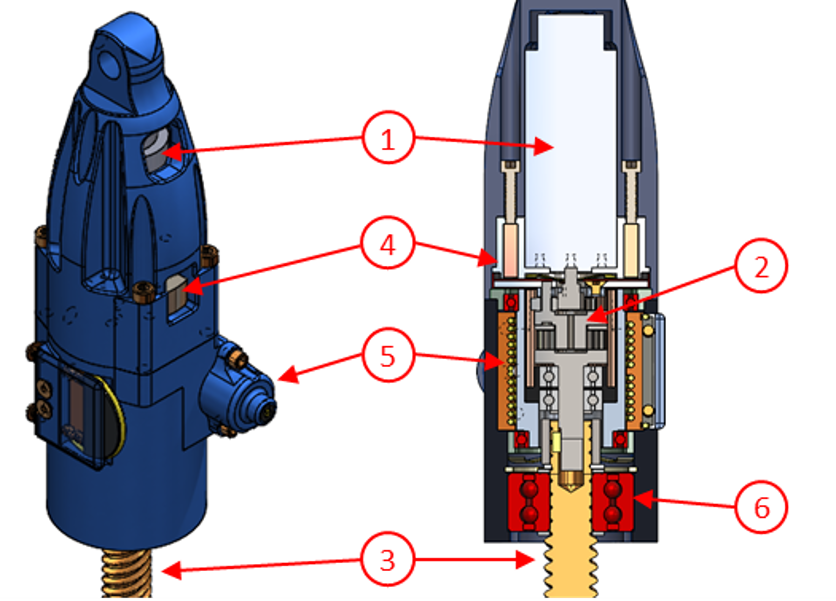
Solid model of novel ECT actuator (left) and cross-sectional view (right). The actuator drivetrain includes a brushless DC motor (1), two-stage planetary-gear transmission (2), and lead screw (3). Two solenoid-actuated clutches provide locking of the first-stage carrier (4) and common ring (5) of the transmission. Large axial loads on the lead screw are transferred to the housing through an angular contact bearing (6).
The ECT is an under-determined transmission with two clutches that ground different components and provide different reduction ratios between input and output. During stance-phase, the common ring-gear is grounded, providing a reduction ratio of 29:1. During swing-phase, the first-stage carrier and second-stage sun are grounded, providing a reduction ratio of 5.4:1.
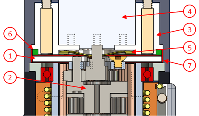
Solid model cross section of the carrier clutch. A ferromagnetic disk clutch armature (1) is collinearly fixed to the first-stage carrier (2) of the planetary gear transmission. A custom solenoid clutch stator (3) is collinearly fixed to the drive motor (4). A wave disk spring (5) separates the armature and stator when the clutch is de-energized. A medium durometer square-cross section O-ring (6) is fixed to the stator and becomes compressed by the armature when the clutch is energized. A plain bearing (7) encircles the armature and O-ring. When the clutch is de-energized, rotation and translation of the armature are constrained by the wave spring and plain bearing, respectively.
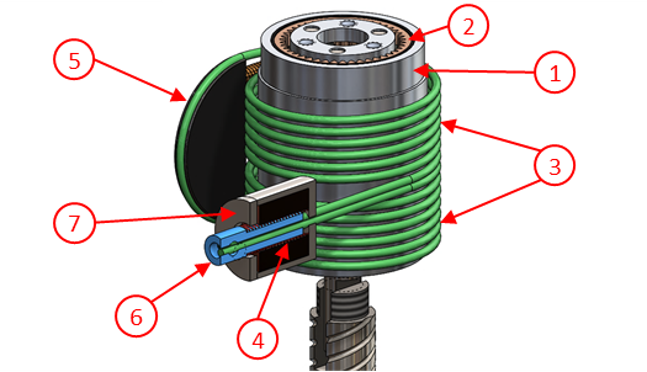
Solid model of ring clutch. An aluminum sleeve (1) is pressed onto the ECT common ring-gear (2). A steel wire rope (3) wraps several times around the aluminum sleeve. The stiff wire rope and compliant aluminum sleeve together form a capstan with a high static friction coefficient. A spring element (4) applies tension to one end of the wire rope while the other end is grounded to the housing by an adjustable anchor point (5). A set screw on the anchor point permits adjustment of the spring element’s preload tension. The distal ends of the spring element and wire rope are fixed to a solenoid armature (6), which rests inside of the solenoid stator (7). Energizing the solenoid disengages the wire rope from the aluminum sleeve.
ECT knee behaviors
Ballistic walking comparison to C-leg 4
C-leg stairs
ECT stairs
ECT walking circuit
End of page