Crystal Plasticity Finite Element Modeling of Fatigue and Creep-Fatigue of Alloy 617 at High Temperature
Research Sponsor:
U.S. Department of Energy (DoE), Nuclear Energy University Programs (NEUP) initiative.
Research Goal and Objectives
Goal:
Develop novel testing and experimentally validated prediction methodologies for creep-dominated creep fatigue response of Alloy 617.
Specific Objectives:
Overview of Computational Tasks:
- Develop CPFE model for Alloy 617 for modeling creep-fatigue deformation between 850°C and 950°C.
- Simulation-based mechanism understanding of CF interaction and life prediction through exercising the microstructure-based CF model.
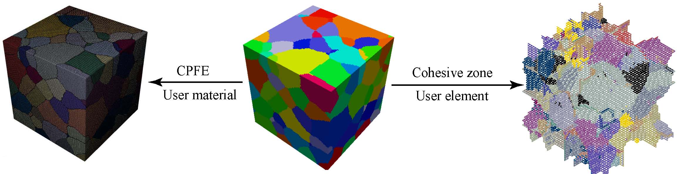
Modeling Approach
Crystal Plasticity Theory:
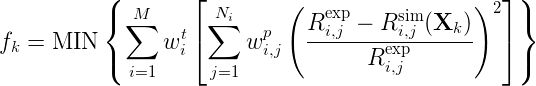
Formulation
![]()
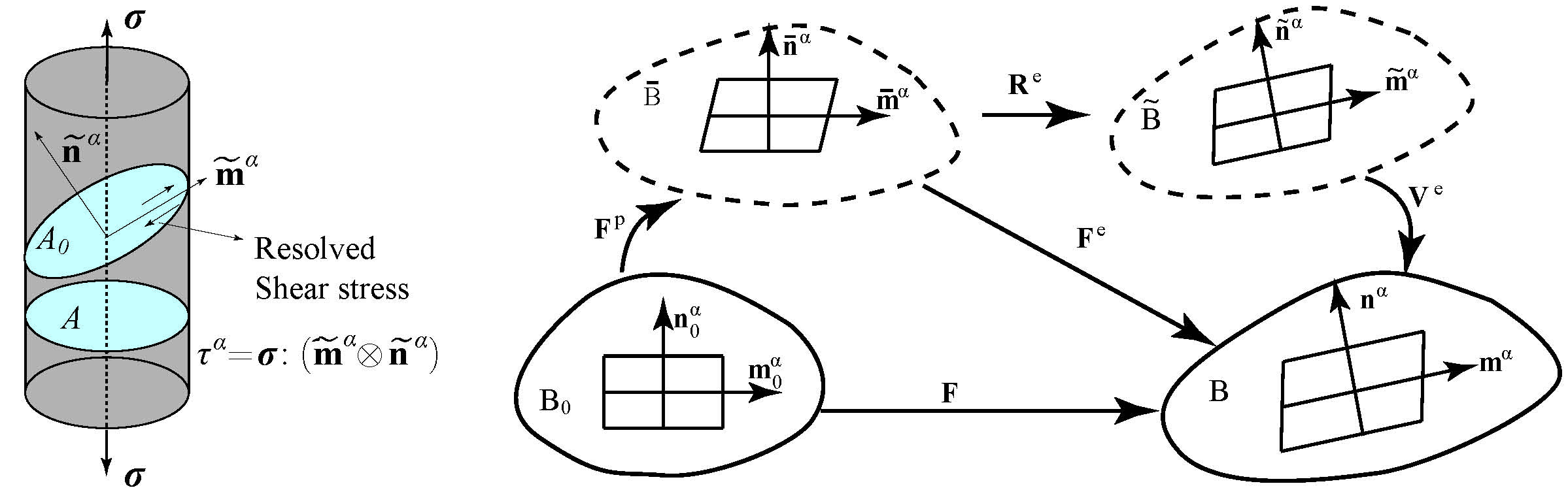
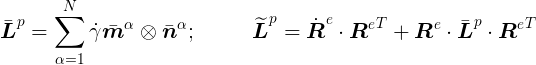
![]()
![]()
Choice of Flow Rule and Evolution Equations:
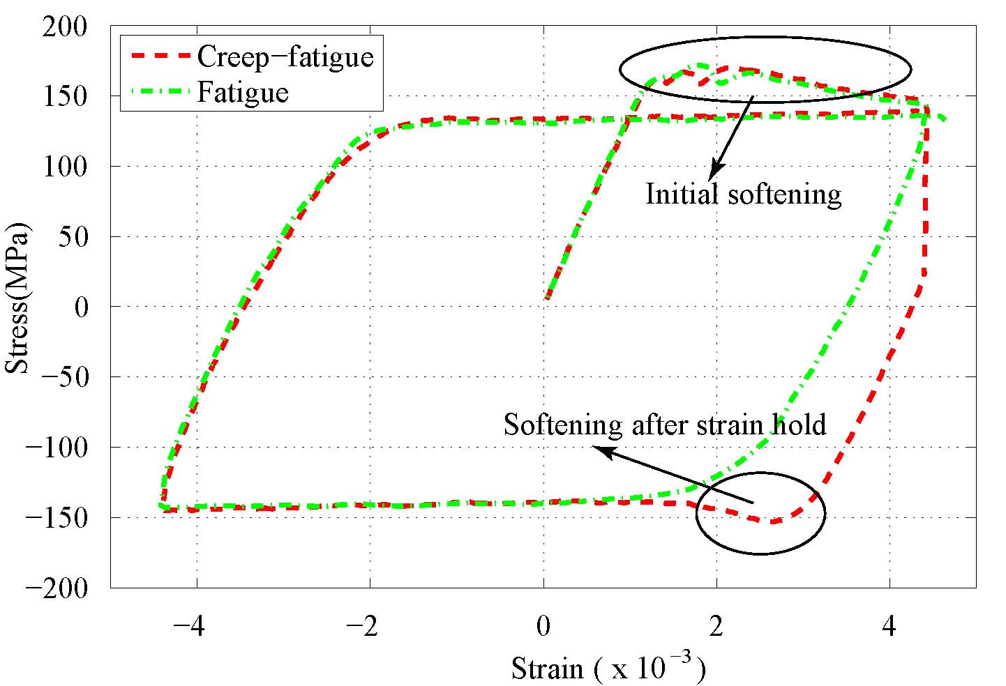
- Softening is observed at the tension part of first load cycle for both fatigue and creep-fatigue tests. Similar softening is also observed in the compression part after strain hold in each cycle of creep-fatigue tests.
- Dislocation velocity increases with stress –> dislocation drag solutes hence extra resistance is produced –> dislocations accumulate enough energy to break solutes away from their equilibrium positions –> resistance drops as more and more solutes start moving together with dislocations.
- Strain hold –> dislocation velocity decreases with stress –> solutes settle down in new equilibrium positions –> softening happens when reverse loading is applied.
- In a fatigue tests, solutes do not have enough time to settle down in their new equilibrium positions as reverse loading follows immediately.
- Activation energy based flow rule for nickel-based alloy subject to cyclic loading at high temperatures (Busso[1996]):
- Slip resistance evolution (Busso[2000]): from statistically stored forest obstacles.
- Backstress evolution (Busso[1996]): from dislocations bowing between obstacles.
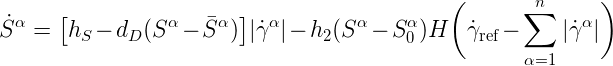
- New slip resistance evolution equation proposed by incorporating an static recovery which reflects the slip resistance changes caused by solute drag creep.

![]()
![]()
Modeling Preparation and Calibration
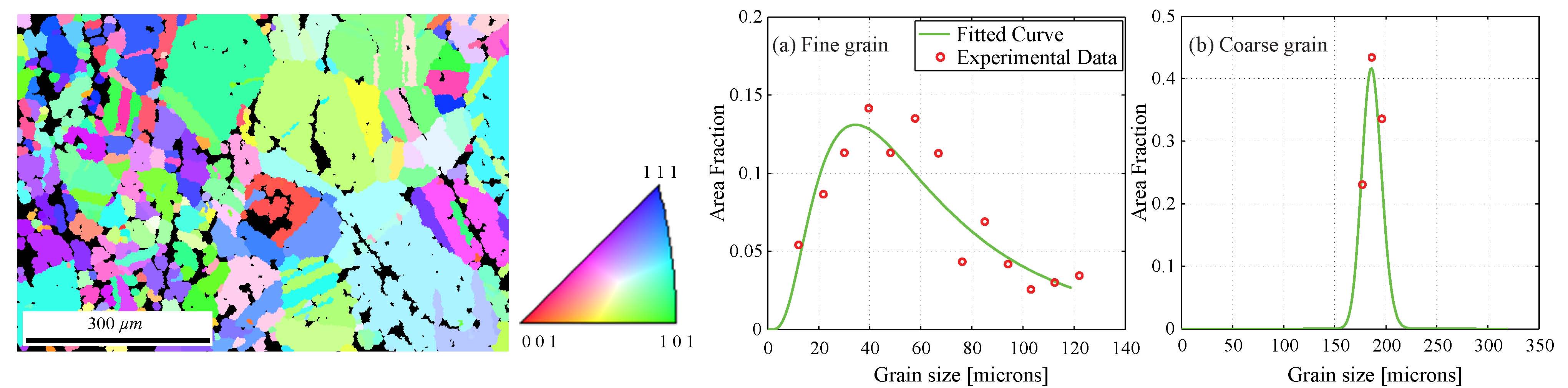
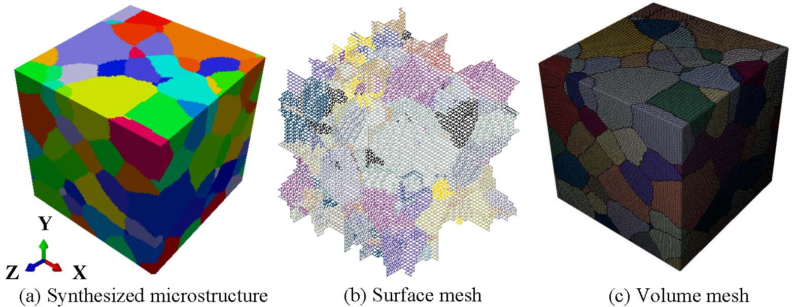
Microstructure reconstruction and meshing
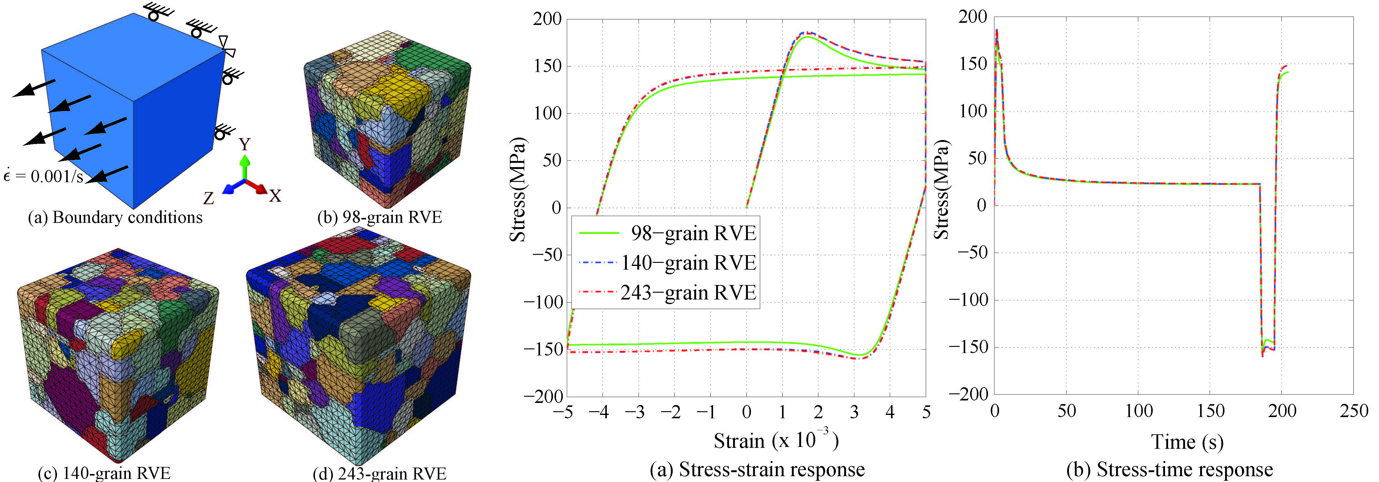
Mesh convergence study
Model parameter calibration
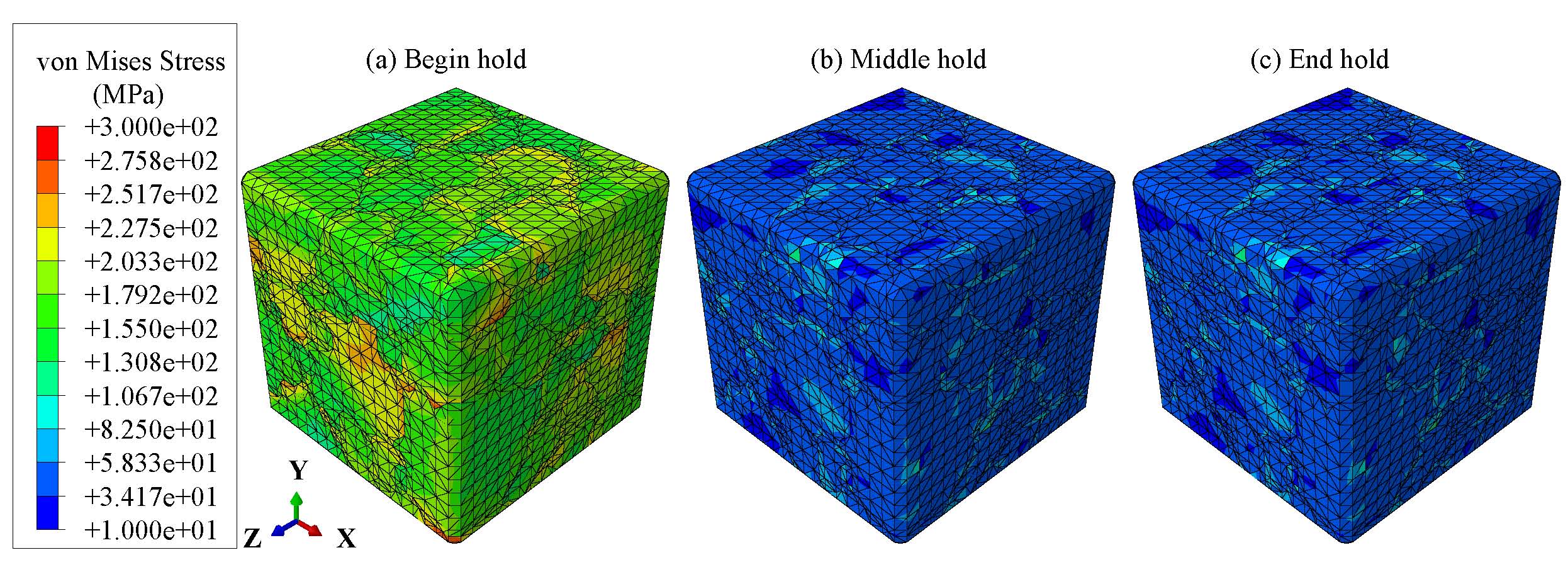
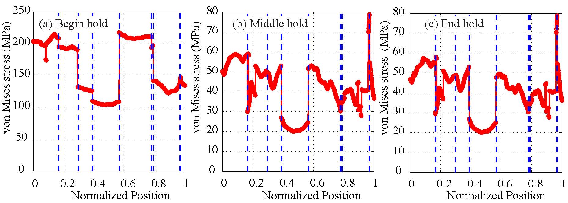
Model Verification and Results Analysis
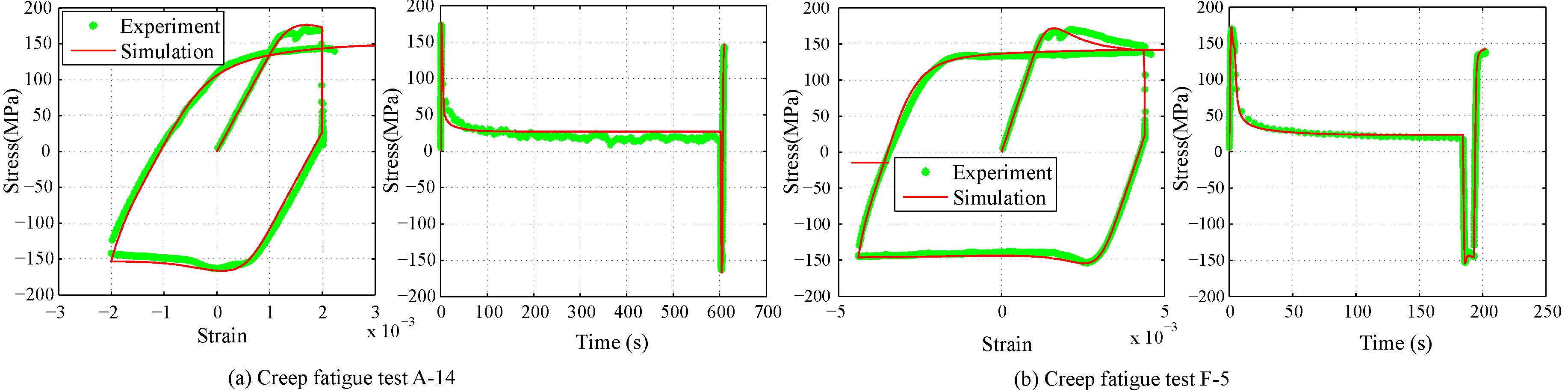
Stress-strain and stress-time response simulation.
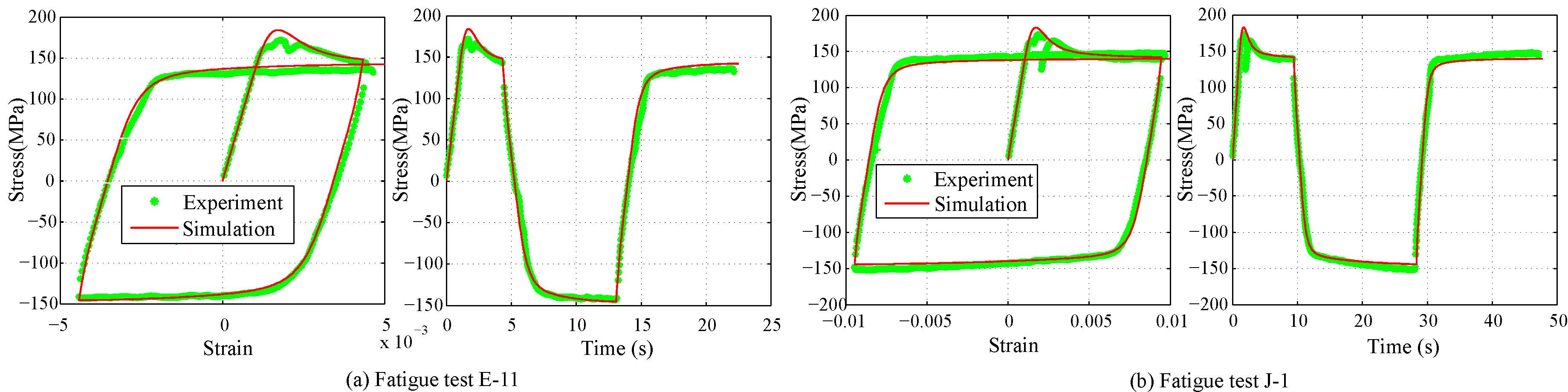
Analysis of CPFE Simulation Results.