SITE NAVIGATION
Design
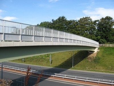
Bridge Choice: The Stringer Bridge
Once our site visit had concluded and our hydrological and geotechnical assessments were performed, it was time to select a bridge type. After thorough research and calculations, our design team decided the stringer bridge was the perfect solution.
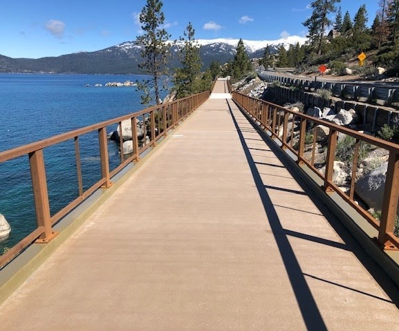
-
- A selection of stringer bridges
Design in a Nutshell
- Two simply supported beams with splices
- Approach Ramps
- Railing and Decking
- Abutments
- Cross-framing
- Foundations
Benefits of the Stringer
- Simplistic, straight-forward design
- Smaller footprint due to minimal weight
- Heavy construction equipment not needed to implement
- Simple on-site assembly can be performed by community members
- Durable, safe, and sustainable
As the primary load-bearing component of the bridge, choosing the beam was an important decision that would influence the rest of our bridge’s configuration. Informed by our prior assessments, some of the major assumptions made during this phase of design included:
- 80’ span length

- 20’ unbraced length
- Dead load:Decking – 30 plf
- Railing – 40 plf
- Steel – 70 plf
- Live load:
- Strength – 255 plf
- Deflection – 25 200 lb
- People and motorcycles
While our bridge design does not encourage motorcycle use, their loading was accounted for to ensure safety. After meticulous calculation and reference of AISC Standards, a total uniform load of 0.3106 kpf was required per beam. With careful consideration, W24x68 Grade 50 steel beams were chosen as the best option.
Superstructure
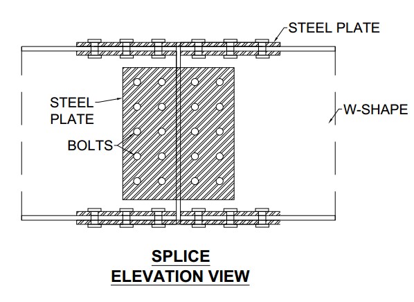
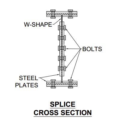
Splices
Our bridge spans 80 feet across a stream. We designed the structure using three 27-foot I-beams connected together to make this span length possible. The splice connections holding the beams together are composed of several bolted plates located on the flanges (top and bottom) and web (middle) of the beams. We used American Institute of Steel Construction (AISC) standards to design these important connections. Our final design consists of:
- ⅞” Diameter A325 Bolts
- ½” thick steel plates
- 44 bolts for each splice
- 20 bolts on the web connection
- 12 bolts on each flange
Cross Frames
We added lateral support to the bridge to reduce the size of our steel I-beams and to provide additional support in case of strong forces against the side of the structure from wind. Our design consists of cross braces made from steel angles (L4x4x3/8) at each end and diaphragms made from steel channels (C12x20.7) spaced every 20 feet along the length of the span.
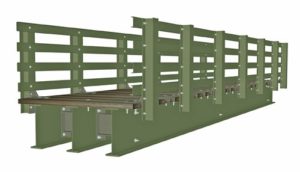
-

- An overhead view of the cross frames
The steel pieces are all connected using A325 bolts and ½ -inch plates. While these components do play a significant role in the overall structural resilience of the bridge, they are not needed to carry any vertical weight from foot travel across the span.
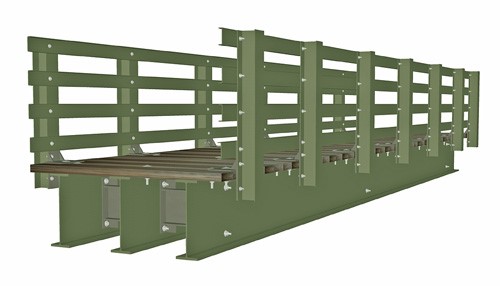
-
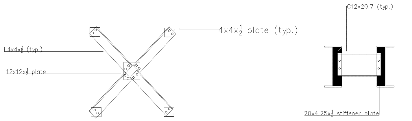
- Detailing for the cross frames
Decking
The walking surface itself not only needs to be strong enough to carry the weight of the foot and motor travel but also durable enough to handle rain and environmental decay. We recommend using composite material for the decking but treated wood is also an option. Here are some advantages and disadvantages of the two materials:
Composite Material
- Advantages:
- Stronger
- More durable
- Disadvantages:
- Not as environmentally friendly
- Not locally available
Treated Wood
- Advantages:
- More environmentally friendly
- Could be treated locally
- Disadvantages:
- Not as strong
- Not as durable
-
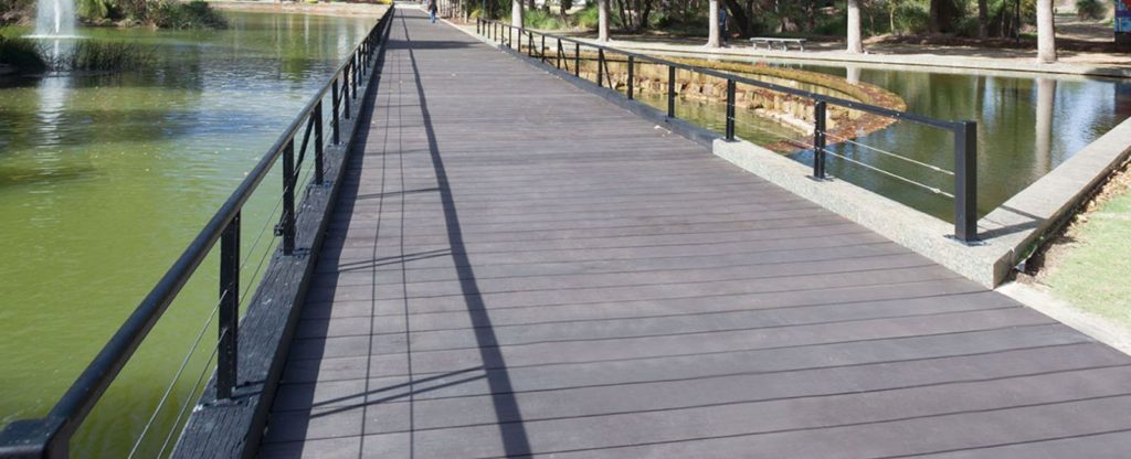
- Sample decking

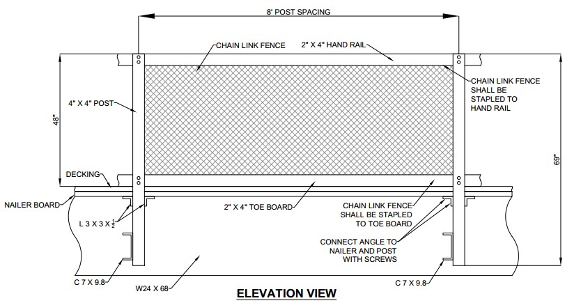
Railings
Railings will consist of wooden posts, handrails, and toe boards. Wood was chosen as a light, environmentally friendly, strong material. Chain link fencing will be stapled to each of the horizontal members. This was chosen to reduce gaps in the railings for safety. The railings are designed to withstand at least 750 pounds of force per AASHTO standards.
Substructure
Ramps
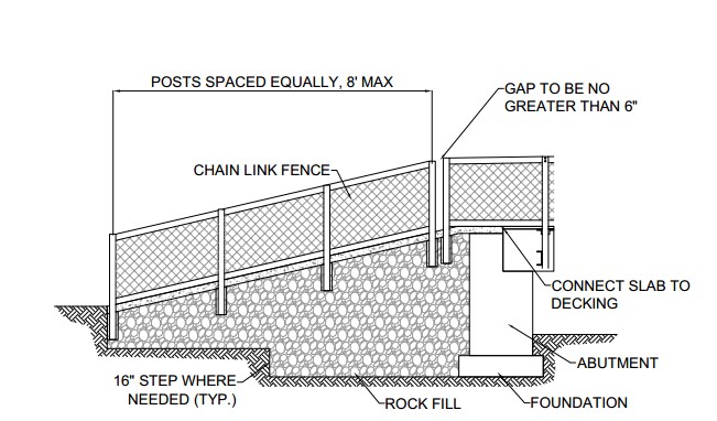 The Bridges to Prosperity Bridge Builder Manual was used to design the approach ramps to the bridge. A maximum slope of 20% is recommended. This is steeper than the maximum ADA slope of 8%, but is still serviceable. The ramps should be kept short enough to service both the clinic and a potential school that may be developed adjacent to the clinic. Concrete masonry blocks will surround lifts of stone, gravel, and sand. The blocks will rest on a shallow concrete footing for stability. The ramp will be capped by a concrete slab.
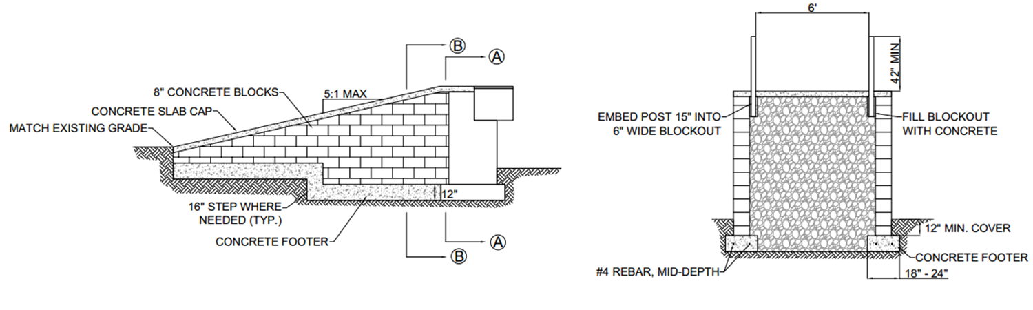
Foundation
Foundation design
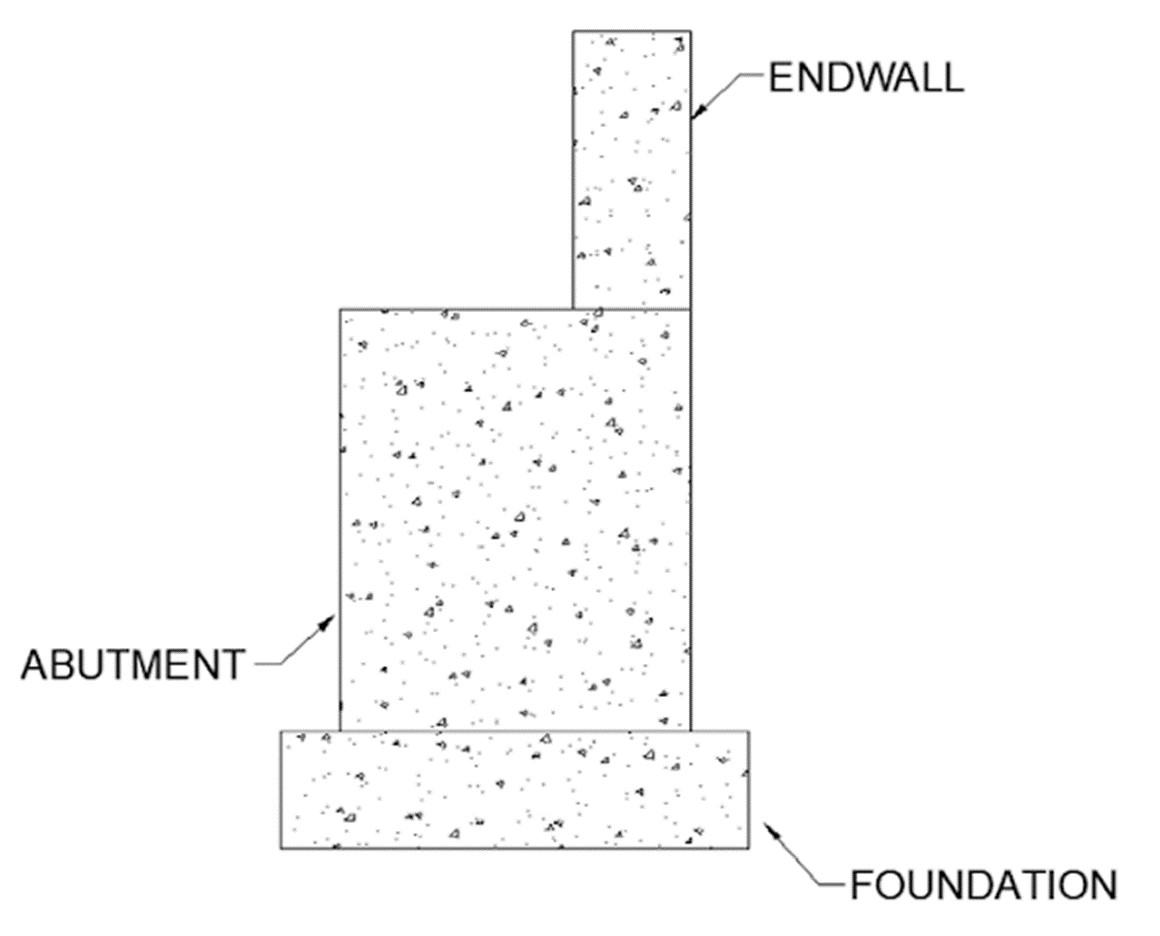
The foundation design relies heavily on the information gathered in the geotechnical assessment, where the maximum gross allowable bearing capacity of the soil is 2000 pounds per square foot. The foundations are constructed of three elements:
- Footing (foundation): Must be large enough to spread the weight of the bridge-foundation-combo over the soil and not exceed 2000 pounds per square foot.
- Abutment: Raises the bridge elevation so that it is above the maximum water level determined in the hydrological assessment.
- Endwall: Acts as a retaining wall to hold back fill material from under the ramps.
The bridge is relatively light compared to the weight of large buildings that foundations often need to support. As such, the calculated footing thickness and area of steel were all below the minimum required, so the minimum specifications were utilized for the design. This resulted in a 1 foot thick footing, 5.3/5.8 foot tall abutments, and 458 feet of total rebar.
Abutment Connections
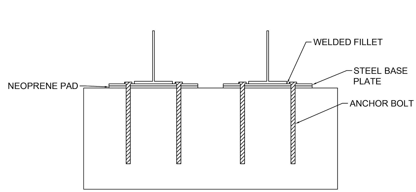
Due to the variation in temperature, slotted holes on one side of the bridge was deemed necessary. Using AASHTO’s Pedestrian Bridge Guidelines, the thermal expansion was estimated to be around 0.76 inches. To allow for this expansion, the slotted holes are designed to be 2.5 inches long with a 1.125 inch width to accommodate the 1 inch anchor bolt. To connect the W24x68 beams to the abutment, a bearing plate, a neoprene pad, and anchor bolts are utilized, as visualized below. The beams are attached with a fillet weld to the bearing plate, which lays on top of the neoprene pad.
-
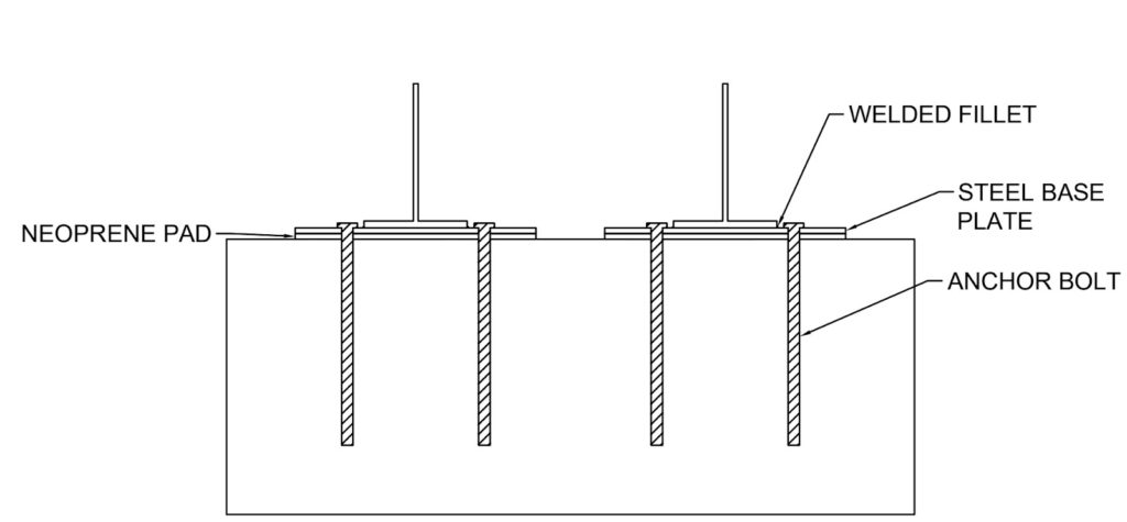
- Beam-to-abutment connection geometry