The Sterling Ranch development is large and encompasses a diverse set of land conditions as well as home types. To achieve maximum efficiency, Sterling Ranch will choose one method to use across entire filings. For this reason, the team analyzed three home types representative of the homes found on the Sterling Ranch property. By analyzing homes with footprints of varying sizes, the team determines if the Tella Firma Foundation will be worthwhile to undertake across an entire filing or if the incumbent over-excavation should continue.
As is the case in all design and estimating, a large number of assumptions are made in the process of determining the worthwhileness of the Tella Firma foundation. By having three different engineering students design three different home types, the team is able to compare designs to catch any unreasonable assumptions and find attributes of the Tella Firma system that change drastically with home size. Each engineering student uses geotechnical data collected from a separate boring pit. By using a diverse set of soil conditions, the team can compare design results and determine if any specific soil properties result in drastic changes in the Tella Firma foundation design.
Loading Calculation Overview
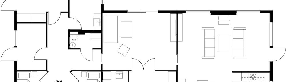
The loadings on each home were calculated from the floor plans provided by Sterling Ranch home builders. These plans can be found at the bottom of the page with a description of each home type. In order to calculate the loads, the team referenced the 2000 Residential Design Guide, Chapter 3: Design Loads for Residential Buildings along with some industry standards provided by RMG Engineers. These loadings are shown in the table below:
Table 2: Dead and Live Loads for Houses in Douglas County, Colorado
| Load Type | Dead Load | Live Load |
| Roof | 15 psf | 30 psf |
| Living | 15 psf | 40 psf |
| Wall | 8 psf | N/A |
| Flooring | 12 psf | N/A |
| Garage | 15 psf | 50 psf |
Each home was then analyzed and uniform live load as well as superimposed dead load was calculated for each slab. A uniform load is not the industry standard for designing homes using a Tella Firma slab. The team uses a uniform load because these loading conditions are conservative and give the needed information for further foundation analysis. Referencing the design objectives, a good cost estimate and recommendation is of higher importance than more exact loading calculations and slab design.
Slab Design Overview
The calculated superimposed dead load and live load are then input into an Excel spreadsheet built to size satisfactory slabs and piers. The first step is sizing the slab to accommodate the loading. Table 3 shows a list of assumptions used as inputs for the slab design process. The spreadsheet is designed to use the direct design method to size a two way concrete slab with uniform loading. Since most Tella Firma slabs are post tensioned, this is also incorporated into the slab calculation spreadsheet. Click here to download the design spreadsheet used in this project.
Table 3: Slab Design Assumptions
| Inputs | Units | Value | Explanation |
| Lx | ft | Varies by home | Length of foundation footprint in x direction |
| Ly | ft | Varies by home | Length of foundation footprint in y direction |
| DL | lb/sft | Varies by home | Superimposed dead load |
| LL | lb/sft | Varies by home | Live Load |
| Ws | lb/cft | 490 | Unit weight of steel |
| Wc | lb/cft | 150 | Unit Weight of concrete |
| PT clear | ft | 0.16667 | Minimum cover on all Post Tension cables |
| f’c | lb/sin | 4500 | Concrete compressive strength |
| f’ci | lb/sin | 3000 | Concrete compressive strength at time of initial stressing |
| FEF | lb/sin | 160,000 | Effective force in tendons (bonded) |
| P | lb/sin | 175 | Precompression pressure |
| Apt | sin | 0.153 | Cross-section area of PT cable (0.5″ diameter) |
| fy | lb/sin | 60,000 | Reinforcing steel yield strength |
| fps | lb/sin | 190,000 | Post tension steel yield strength |
With these inputs, the spreadsheet is manipulated to find a combination of concrete thickness and reinforcing that handles the applied loads. The slab is optimized to be as thin as possible to minimize cost. Safety is checked through slab strength and serviceability in accordance with the ACI building codes. The slab is checked on seven attributes: Stressing transfer after jacking PT tendons, Minimum required reinforcing, Compression service stress, Tension service stress, Service deflections, Moment, and Punching shear. The checks are tabulated in Table 4.
Standard rebar is required in addition to the post tension cables to reinforce the slab. A report of the necessary reinforcing is given for each home design in the following section. The direct design method treats all interior spans as identical. Thus, a reinforcing calculation is only needed for two spans in each direction, an exterior span and a typical interior span. As long as the structure has at least two spans in each direction, the direct design method can be used for any size building without further calculations thanks to this property.
Table 4: Slab Design Checks
| Check | Units | Success? |
| Initial Stressing Transfer | lb/sin | TRUE |
| Min reinforcing per span | sin | TRUE |
| Service Stress (compression) | lb/sin | TRUE |
| Service Stress (tension) | lb | TRUE |
| Service deflections | in | TRUE |
| Slab Mu Strength | lb/ft | TRUE |
| Slab Punching Shear | lb | TRUE |
Pier Design Overview
After the slab has been designed, the piers can be designed. Based on the length of each slab span and the applied loading, a new loading is calculated for each pier. The assumption has already been made that the loading is uniform. By extending this assumption into the pier design, only one set of calculations is needed to design a typical pier. The team assumed the worst case scenario, the interior pier loading, for each pier of the individual foundations. It is likely that a detailed design that considers each pier independently would be able to save further money as compared to this analysis.
The pier spreadsheet was designed to use an allowable stress design technique from ACI 336.3R – 93. This design process comes with a new set of assumptions, which are detailed in Table 5. A majority of the inputs for this spreadsheet are soil properties which were calculated from the aforementioned geotechnical report that was conducted on Sterling Ranch soil.
Table 5: Pier Design Assumptions
| Inputs | Units | Value | Explanation |
| DL | lb | Varies by home | Dead Load (from slab calculation) |
| LL | lb | Varies by home | Live Load (from slab calculation) |
| W | lb/sft | 16 | Lateral Wind Load |
| Yw | lb/cft | 62.4 | Weight of Water |
| qp | lb/sft | 20000 | Soil unit bearing pressure |
| fo | lb/sft | 2000 | Soil average side friction |
| Su | lb/sft | 1500 | undrained soil strength |
| COLE | ft/ft | 1.1 | Soil COLE value |
| f’c | lb/sin | 3000 | concrete compressive strength |
| fy | lb/sin | 60,000 | reinforcing steel yield strength |
| FS1 | n/a | 3 | Soil Bearing factor of safety |
| FS2 | n/a | 3 | Side Resistance factor of safety |
Another assumption of the pier spreadsheet calculation is that the pier cannot be terminated early due to shallow bedrock. This is a worst case scenario, as any piers located above shallow solid bedrock could be socketed into the bedrock level and would require less concrete than expected. Similar to the slab design, the pier spreadsheet was manipulated to find the lowest cost pier design that could withstand the applied loads and achieve the necessary safety checks. The pier design was checked on seven attributes: Concrete compressive strength, Bending moment, Lateral shear, Bearing, Uplift, and two forms of Combined flexure / axial loading. The checks can be found in Table 6. To resist tensile strain created by uplift forces, vertical steel reinforcement was also designed.
Table 6: Pier Design Checks
| Checks | Source | Success? | units | ||
| Compressive | ACI 318-19 Table 13.4.2.1 | 1 | lb | ||
| Moment | ACI 318-19, 14.5.2.1a | 1 | lb*in | ||
| Shear | ACI 318-19, Table 14.5.5.1a | 1 | lb | ||
| Bearing | ACI Pier Design, 3-1 | 1 | lb | ||
| Uplift | ACI Pier Design, 3-5 | 1 | lb | ||
| Combined flexure / axial a | ACI 318-19 Table 14.5.4.1a | 1 | lb/sin | ||
| Combined flexure / axial b | ACI 318-19 Table 14.5.4.1b | 1 | lb/lb | ||