Purpose
This report holds the results of a geotechnical exploration for Filing 3B of the Sterling Ranch Development in Douglas County, Colorado. The exploration was performed in order to inform design criteria of foundation solutions, specifically those pertaining the design of a drilled pier foundation system. This report will not comment on any additional concepts outside of drilled pier construction. The exploration is meant to represent the soil beneath one house. The report and its data are used to inform the foundation design done by the team. Data gathered from the exploration is attached and summarized in Figure A1 and Figure A2.
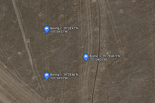
Figure A1. Boring Coordinates on Map
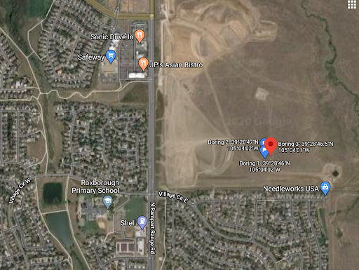
Figure A2. Boring Locations with Surrounding Area
Site Conditions
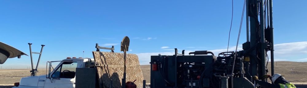
The exploration was performed on January 13, 2020. The drill site is located within Sterling Ranch’s Filing 3B. Located east of N Rampart Range Rd and west of Roxborough Park Rd, the site was also just north of the existing Roxborough development. The site was heavily disturbed as over-excavation was being done, but the drilling occurred outside of the disturbed soil such that native soil could be captured.
Field Exploration
Subsurface conditions were explored by drilling three holes spaced in an approximate equilateral triangle each 50 feet apart (See “Site Plan and Boring Location” in Figure A1). With assistance from Odell Drilling Inc., a 1.378 in diameter split spoon sampler was driven into the ground by the 30-inch drop of an automatic hammer that weighed 140 pounds. The blow counts were recorded for every 6 inches of captured soil until 18 total inches were captured. These 18-inch samples were collected every 5 feet down to 20 feet below ground. In total, four 18-inch samples were taken from each boring with their blow counts labeled. The final boring logs for each boring in Figure B1, B2, and B3 combine the results of the field exploration with the results of the lab tests.
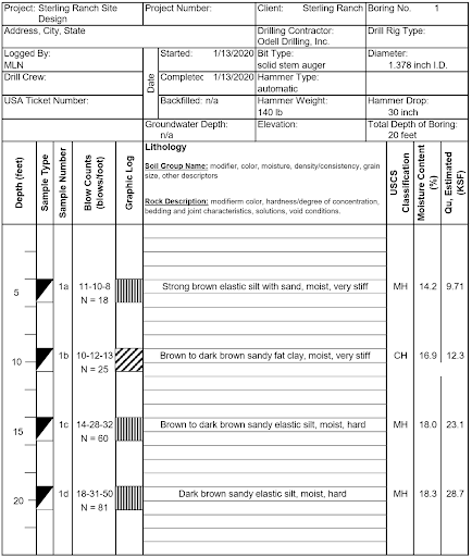
Figure B1. Boring Log, Hole 1
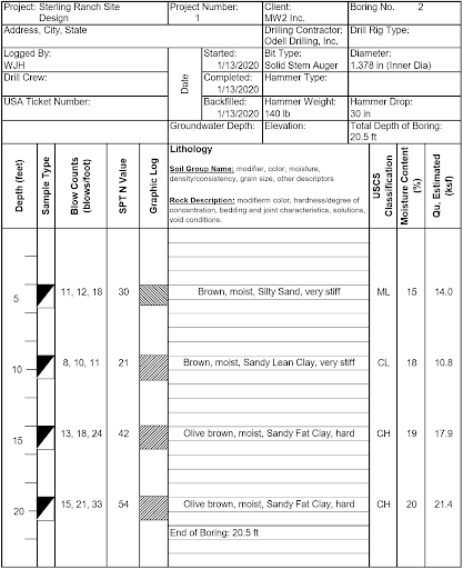
Figure B2. Boring Log, Hole 2
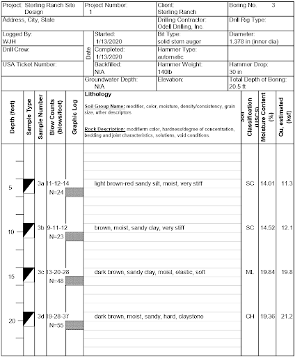
Figure B3. Boring Log, Hole 3
Laboratory Testing
Once the samples were transported back to Nashville, the team member performed a visual classification, a wash sieve test, and an Atterberg Limits test on all four samples belonging to one boring. The wash sieve test allowed the team to be able to determine the grain size distribution in each sample, which is needed for exact classification. The Atterberg Limits test determined the plasticity of each sample. High plasticity indices were expected due to the assumed clay content and were found as shown in the data in Tables C1, C2, C3. A shrink-swell test was not performed because the split spoon sampler yields disturbed samples. Disturbed samples are not suitable because they are already somewhat compacted from the sampling process. The shrink-swell results of the report from AG Wassenaar provided to us by Sterling Ranch were used to get the pier uplift values.
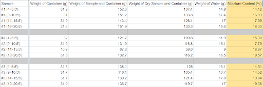
Table C1. Moisture Content Data
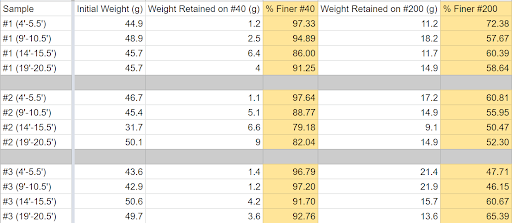
Table C2. Wash Sieve Test Data
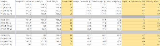
Table C3. Atterberg Limits Data
Foundation Design Criteria
For a Tella Firma foundation, the slab is elevated off the ground, thus the geotechnical report will not inform any part of the slab design. However, this report will give criteria for pier design, specifically the bearing and uplift.
The ultimate bearing capacity was calculated from as a direct relationship to Standard Penetration Blow Count (N). The relation is shown below:
Table 1: Qu as a Function of SPT
| Soil Type | Qu (kPa) | Reference(s) |
| Fine-grained soil | 58*N0.72 | Hara et al. (1974)
Kuhawy and Mayne (1990) |
Uplift forces are also considered in foundation design when expansive soils are expected. Uplift forces acting on the pier can be caused by either buoyancy effects or uplift swell pressure. Buoyancy considers the fact that soil has become so saturated that the pier has lost frictional contact with the soil and essentially floats upward. In a worst case scenario, the uplift force would be based on water pressure acting on the base of the pier with a fluid head equal to the full length of the pier. This force must be resisted by the service dead load acting on the pier.
Uplift swell pressure creates an upward frictional force when expansive soils become saturated. As the soil expands, it squeezes the embedded surface area of the pier upward based on the empirical formula:
Soil Uplift Pressure = 100 (Plasticity Index) – 1000 in psf
This force must also be resisted by the service dead load acting on the pier. Soil uplift pressure can also cause tensile strain on the pier itself if the uplift pressure only interacts with a portion of the pier. This tensile force should be considered when determining the need for vertical reinforcement in the pier.
Limitations
The scope of work for this report is limited. It is strictly meant to inform foundation design and assumes no other solutions. Therefore, it does not concern any cut and fill techniques or other recommendations. Also, we only surveyed a very small patch of land that represented the land below one home. It is unwise to extrapolate that data to all the land Sterling Ranch owns. However, we are assuming that the subsurface conditions would be consistent throughout Sterling Ranch for our cost estimate.