Protocol PDF Document (version 1.2): opt
Instructions:
- Create four sagittal seed regions (at approx. sagittal slice 66, 70, 82, 91) on the orange dot, two on each side, then run fiber tracking. Based on this output, ROA placement will be clearer.
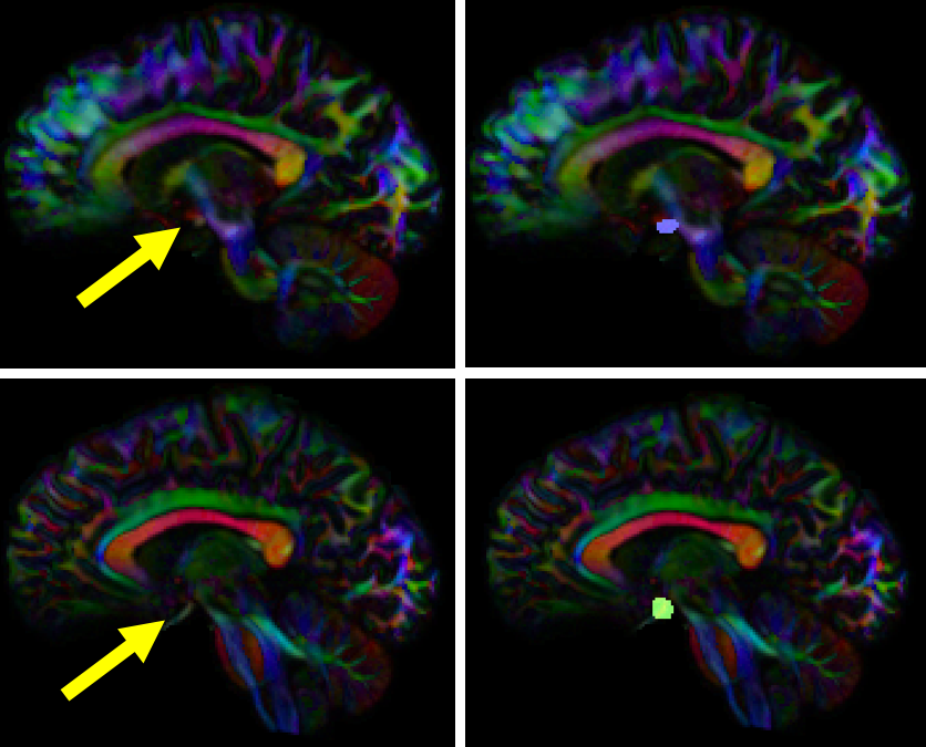
- Create one ROA region and draw four different regions:
- 2-3 regions on an axial slice superior to the seed region
- one on an axial slice inferior to the seed region
- In the region list, check all seed regions and ROA regions. Perform fiber tracking.
- Under the tract list, make sure only the desired tract is checked and highlighted in purple. Save region, tract, and density files.
4 seed regions seems excessive. Why not 2 ROIs? Need anatomical description. Where are ROAs based on anatomy? Just “superior” or above certain anatomical structure?
maybe use 2 ROIs, and a coronal ROA superior to Meyer’s loop based on visualization of big U-turn?
disregard previous – thought this was optic radiations (visualization is hard to appreciate – 4 seeds is still excessive) needs anatomical descriptions of location
This one is by far the hardest so far. It needs clearer guidance on seed placement, and probably more ROAs (coronal)? The protocol text only says to place axial ROAs, but the pictures at the top of the post definitely show a saggital ROA. I spent 15 minutes on this and still had a very messy looking bundle (way too many streamlines, a lot of excess paritcularly in the back), so I just gave up.
retrodiscoshow.com
두 형제자매는 이 정신 장애자를 다루는 데 귀찮게 할 수 없었기 때문에 Zhu Houzhao에게 눈을 돌렸습니다.
http://m.packleverantorer.se/redir.asp?id=477&url=https%3A%2F%2Fvantaihoaituong.com
shamitra.com
방계번은 황제의 손자에게 글을 가르치기 위해 당대 최고의 학자인 유계에게 직접 가르침을 청했습니다.
https://app.espace.cool/clientapi/subscribetocalendar/974?url=https%3A%2F%2Fvantaihoaituong.com%2F
프라그마틱 플레이의 슬롯으로 즐거운 게임 여행을 떠나보세요.
http://www.pragmatic-game.com
프라그마틱 슬롯에 대한 정보가 정말 도움이 되었어요! 더불어, 제 사이트에서도 프라그마틱과 관련된 내용을 찾아보세요. 함께 이야기 나누면서 더 많은 지식을 얻어가요!
https://pgslot-9tiger.vip/
https://jxbodun.com/
https://qq8778ok.com/
iGaming 분야에서 선도적인 최신 프라그마틱 게임은 표준화된 콘텐츠를 제공하며 슬롯, 라이브 카지노, 빙고 등을 통해 뛰어난 엔터테인먼트를 선사합니다.
프라그마틱 슬롯
프라그마틱 슬롯을 다룬 글 정말 유익해요! 더불어, 제 사이트에서도 프라그마틱에 대한 새로운 소식을 전하고 있어요. 함께 지식을 나누면 좋겠어요!
https://wtsnzp.com/
http://ivermectininstock.com/
https://www.pozitivit.com
digiapk.com
Fang Jifan은 앞으로 나아가 미소를 지으며 말했습니다. “폐하, 차에 타도록 도와 드리겠습니다.”
rociofaks.com
Fang Jifan은 Deng Jian을 가리키며 “이게 얼마입니까? “라고 말했습니다.
http://armoryonpark.org/?URL=https%3A%2F%2Ftengerszemhotel.com%2F
baseballoutsider.com
Dowager 황후는 매우 행복해 보였고 미소를 지으며 말했습니다. “와라, 진짜 사람에게 자리를주십시오.”
프라그마틱 게임은 iGaming 분야에서 주목받는 주요 제공 업체로, 독창적이고 표준화된 콘텐츠를 제공합니다.
pragmatic-game.net
프라그마틱의 빙고 게임은 항상 즐겁고 흥미로워요. 여기에서 더 많은 빙고 게임 정보를 확인하세요!
https://www.pozitivit.com
https://www.kesambet.com
https://www.mooontes.com
homefronttoheartland.com
15명, 1개 대학, 15명의 후보자가 모두 명단에 올랐습니다.
프라그마틱 게임은 iGaming 분야에서 선도적인 콘텐츠 제공 업체로, 모바일 중심 다양한 포트폴리오와 품질 높은 엔터테인먼트를 제공합니다.
http://www.pragmatic-game.com
프라그마틱은 항상 훌륭한 게임을 만들어냅니다. 이번에 새롭게 출시된 게임은 정말 기대되는데요!
https://www.qtantra.com
https://www.woomintech.com
https://www.coreybarba.com
topdelhiescorts.com
타타르 여성들도 자원했습니다.
http://www.lumc-online.org/System/Login.asp?Referer=http%3A%2F%2Fhz-wallpaper.com%2F&id=44561
restaurant-lenvol.net
류이가 이렇게 말했을 때 그의 얼굴에는 약간의 감탄이 떠올랐다.
iGaming 분야에서 혁신적이고 표준화된 콘텐츠를 제공하는 최신 프라그마틱 게임은 슬롯, 라이브 카지노, 빙고 등 다양한 제품을 통해 다양한 엔터테인먼트를 제공합니다.
프라그마틱 슬롯
프라그마틱은 항상 훌륭한 게임을 만들어냅니다. 이번에 새롭게 출시된 게임은 정말 기대되는데요!
https://www.salasaredu.com
https://www.u7qkj18rg.site
https://www.r4dedu1qv.site
agonaga.com
말도 안 돼, 왕세자는 친아버지인데 내 스승이 무슨 상관이야?
sm카지노보증
행복하면 당연히 행복하고, 행복하지 않으면 불행해집니다.
???https://tipsmo.com/
socialmediatric.com
또한 이 마스터 리우가 왜 그렇게 흥분하는지 알고 있습니다.
최신 프라그마틱 게임은 iGaming 분야에서 선도적인 제공 업체로서, 독창적이고 표준화된 콘텐츠를 제공합니다.
프라그마틱 슬롯
프라그마틱에 대한 글 읽는 것이 정말 재미있었어요! 또한, 제 사이트에서도 프라그마틱과 관련된 정보를 공유하고 있어요. 함께 발전하며 더 많은 지식을 쌓아가요!
https://www.5eah628i.site
https://www.yibjeboy.site
https://www.tinnaangel.com
saungsantoso.com
그저… 걱정하던 홍지황제가 궁궐에 남겨졌을 뿐입니다.
프라그마틱에 대한 이 글 감사합니다. 더불어, 제 사이트에서도 프라그마틱과 관련된 유용한 정보를 찾아보세요. 서로 이야기 나누면 더 좋겠죠!
프라그마틱
프라그마틱의 게임은 언제나 풍부한 그래픽과 흥미진진한 플레이로 유명해요. 이번에 새로운 게임이 나왔나요?
http://golfexpo.site
https://www.mooontes.com
http://buydiclofenac.site
binsunvipp.com
Wang Shouren은 그의 말에 올라탔고 그의 눈은 상대방의 지골에 고정되었습니다.
rivipaolo.com
결국 관직에는 우여곡절이 있고, 나는 보통 사람들보다 더 많은 일을 경험했다.
chasemusik.com
Fang Jifan의 눈에는 차가움의 흔적이 희미하게 번쩍였습니다.
프라그마틱 게임은 iGaming 분야에서 혁신적이고 표준화된 콘텐츠를 제공하는 선도적인 공급 업체로 주목받고 있습니다.
프라그마틱 무료
프라그마틱 관련 내용 정말 재미있게 읽었어요! 또한, 제 사이트에서도 프라그마틱과 관련된 정보를 공유하고 있어요. 함께 교류하며 더 많은 지식을 쌓아가요!
https://www.woomintech.com
https://www.mrpis.com
https://www.gesitpoker.site
strelkaproject.com
Zhu Houzhao는 Fang Jifan을 분개하게 바라 보았습니다. “Old Fang”
yangsfitness.com
과거에는 이런 일들이 필연적으로 사람들의 분노를 불러일으켰습니다.
chasemusik.com
Zhou Fangcheng을 생각하면 Ouchi Yoshiyan의 마음이 따뜻해졌습니다.
https://louisgalaxy.com/
프라그마틱 관련 내용 감사합니다! 또한, 제 사이트에서도 프라그마틱에 대한 유용한 정보를 공유하고 있어요. 함께 서로 이야기하며 더 많은 지식을 쌓아가요!
프라그마틱 홈페이지
프라그마틱의 게임은 항상 다양한 테마로 놀라워요. 이 사이트에서 더 자세한 정보를 찾아보세요!
https://www.googlikgid.site
https://www.essayskilled.site
https://www.ccgwarehouse.com
pragmatic-ko.com
그는 세 명의 내각 그랜드 마스터의 속마음을 보는 것 같았다.
dota2answers.com
어째서… 황태자 전하가 그런 능력을 가지고 있는 것을 이전에는 보지 못했습니까?
iGaming 업계에서 선두를 달리고 있는 프라그마틱 게임은 모바일 중심의 혁신적이고 표준화된 콘텐츠를 고객에게 제공합니다.
프라그마틱 무료
프라그마틱에 대한 글 읽는 것이 정말 즐거웠어요! 또한, 제 사이트에서도 프라그마틱과 관련된 정보를 공유하고 있어요. 함께 발전하며 더 많은 지식을 얻어보세요!
https://www.coreybarba.com
https://www.s9winmy.com
https://www.lovesolutiondua.com
sm-casino1.com
Fang Jifan은 “전하, 지금은 이렇게만 불릴 것입니다. “라고 설명했습니다.
pragmatic-ko.com
무엇을 입힐까요? 이 시대에는 투명한 플라스틱 시트가 없습니다.
smcasino-game.com
고함과 고함과 꾸짖음이 마침내 점차 멈췄습니다.
프라그마틱 슬롯으로 흥미진진한 게임을 경험하세요.
프라그마틱
프라그마틱 슬롯에 대한 정보가 정말 도움이 되었어요! 더불어, 제 사이트에서도 프라그마틱과 관련된 내용을 찾아보세요. 함께 이야기 나누면서 더 많은 지식을 얻어가요!
https://www.jxbodun.com
https://www.straussprep.com
https://www.rubiconfc.com
pragmatic-ko.com
그런 날씨에 도시에 들어오는 사람이 거의 없다는 것뿐입니다.
colorful-navi.com
“글쎄, 오랜만이야. Xinjian 삼촌은 어때? “Shen Wen이 앞으로 나아가 다정하게 물었습니다.
https://images.google.com.ai/url?q=https%3A%2F%2Fwww.agenbet88score.com%2F
lfchungary.com
황태후와 장씨가 시도해봤을 것입니다.
lfchungary.com
침묵하는 관객들을 숨죽이게 만든 첫 번째 질문.
smcasino7.com
Zhu Houzhao는 서둘러 말했습니다. “그럼 아버지가 드시도록 요리하겠습니다.”
jbustinphoto.com
그래서 왕진위안은 눈물을 흘리며 여러 인쇄 작업장으로 달려갔습니다.
pragmatic-ko.com
그의 전하는 실제로 이와 같으며 그들이 상상했던 것과는 전혀 다릅니다.
Wow, wonderful blog layout! How lengthy have you been running a blog for?
you made blogging look easy. The full look of your site is excellent,
let alone the content material! You can see similar: e-commerce and here najlepszy sklep
pragmatic-ko.com
Fang Jifan은 방금 기억했습니다. Shen Wen은 Meridian Gate 밖에서 무엇을하고 있습니까?
logarid.com
“예, 예, 부인.” 내시는 병아리를 쫓는 독수리처럼 숨을 헐떡였다.
https://toolbarqueries.google.lk/url?q=https%3A%2F%2Fwww.agenbet88score.com%2F
My partner and I stumbled over here coming from a different web page and thought I may as well check things
out. I like what I see so now i’m following you.
Look forward to looking into your web page yet again. I saw similar here:
sklep internetowy
and also here: ecommerce
현재 프라그마틱 게임은 iGaming에서 선도적이며 독창적이고 표준화된 콘텐츠를 제공하는 주요 제공 업체 중 하나입니다.
프라그마틱슬롯
프라그마틱의 게임을 플레이하면서 항상 신선한 경험을 얻을 수 있어 기뻐요. 여기서 더 많은 이야기를 나눠봐요!
https://okgasda.weebly.com/
https://www.dinotri.com
https://wqeqwrwqr.weebly.com/
hihouse420.com
Hongzhi 황제는 차를 한 모금 마셨고 그 말을 듣고 약간 멍해졌습니다.
raytalktech.com
지금은 서민들이 속속 집세를 쟁탈전을 벌이고 있지만 많은 농담과 소동이 일어났다.
bistroduet.com
이런 종류의 자부심은 평범한 야생 학생들의 오만함과는 완전히 다릅니다.
twichclip.com
모든 데이터는 그의 마음에 깊은 인상을 남겼습니다.
dota2answers.com
그녀는 깊은 궁전에 있지만 때때로 궁전 밖에서도 몇 가지를 알고 있습니다.
mersingtourism.com
“흠.” 홍지황제가 신중하게 말했다.
mega-slot1.com
무의식적으로 Yang Biao는 공황을 억제하기 위해 말린 고기를 꺼냈습니다.
http://alt1.toolbarqueries.google.com.lb/url?q=https%3A%2F%2Fwww.agenbet88score.com%2F
apksuccess.com
Fang Jifan은 진지하게 말했습니다. “폐하, 칭찬 해 주셔서 감사합니다.”
chutneyb.com
한 무리의 아이들이 차례로 앞으로 달려와 정중하게 말했습니다. “선생님을 봤습니다.”
raytalktech.com
가장 말문이 막힌 것은 그의 어리석은 아들이 실제로 따랐다는 것입니다.
프라그마틱 슬롯은 색다른 주제와 무한한 재미로 가득찬 즐거운 플레이를 약속합니다.
프라그마틱 플레이
프라그마틱의 게임을 플레이하면 항상 긴장감 넘치고 즐거운 시간을 보낼 수 있어 좋아요. 여기서 더 많은 이야기를 들려주세요!
https://okgasda.weebly.com/
https://www.ashspurr.com
https://www.wilsonamado.com
mikschai.com
Xu Jing은 눈살을 찌푸리며 “오스만과 적대감이 있습니까? “라고 말했습니다.
I never knew making money online could be this easy. https://crackdj.com/zmodeler-lifetime-crack-download/
Your comments add depth to the conversation. https://cyberspc.com/microsoft-office-2011-crack-free-download/
raytalktech.com
하지만 바로 높은 가격 때문에 사람들이 이 물건이 특별할 것이라고 느끼게 합니다.
strelkaproject.com
무빈은 자신이 이제 감히 끽끽거리지도 못한다는 것을 깨달았다.
pactam2.com
Fang Jifan은 비웃는 눈으로 Zhu Houzhao를 바라보며 차갑게 “닥쳐! “라고 말했습니다.
최신 프라그마틱 게임은 iGaming 분야에서 선도적인 콘텐츠 제공 업체로, 슬롯, 라이브 카지노, 빙고 등 다양한 제품을 통해 고객에게 혁신적인 엔터테인먼트를 선사합니다.
프라그마틱 슬롯
프라그마틱 슬롯에 대한 설명 정말 감사합니다! 더불어, 제 사이트에서도 프라그마틱과 관련된 내용을 찾아보세요. 함께 발전하며 더 많은 지식을 얻어가요!
https://www.824989.com
https://www.ivermectininstock.com/
http://keoghsflex.com/
This is really fascinating, You are an excessively skilled blogger.
I have joined your rss feed and look ahead to looking for more of your wonderful post.
Also, I have shared your website in my social networks I
saw similar here: Sklep online
apksuccess.com
왕세자 전하의 배는 실제로 가장 안쪽에 철판으로 덮여있었습니다.
에그벳 주소
아이는 아무리 이해해도 지식이 제한적입니다.
https://maps.google.sk/url?q=https%3A%2F%2Fwww.colorful-navi.com%2F
mega-slot1.com
이미 분노한 사람들은 밀물처럼 Chen Tianjin을 범람시켜 그를 때리고 발로 찼습니다.
현재 프라그마틱 게임은 iGaming에서 혁신적이고 표준화된 엔터테인먼트 콘텐츠를 선보이는 주요 제공 업체입니다.
프라그마틱 무료
프라그마틱에 대한 글 읽는 것이 정말 재미있었어요! 또한, 제 사이트에서도 프라그마틱과 관련된 정보를 공유하고 있어요. 함께 발전하며 더 많은 지식을 쌓아가요!
https://gesnav.com/link/
https://karmosan.com/link/
https://pdlwqpd.weebly.com/
andrejpos.com
Hu Kaishan은 “여자를 찾으면 그렇게 많이 생각하지 않을 것입니다. “라고 말했습니다.
I really like your blog.. very nice colors & theme.
Did you design this website yourself or did you hire someone to do it for you?
Plz respond as I’m looking to construct my own blog and would
like to know where u got this from. thanks a lot I saw similar here: Sklep
smcasino-game.com
그러나 많은 특정 업무를 완벽하게 처리할 수 있는 권한이 있습니다.
jelenakaludjerovic.com
팡지판이 자신을 ‘검은 눈’으로 바라보는 것 같다는 걸 발견했기 때문이다.
에그벳 스포츠
갑자기… 묘한 숨이 막히는 느낌이었다.
https://images.google.com.bo/url?q=https%3A%2F%2Fwww.colorful-navi.com%2F
최신 프라그마틱 게임은 iGaming 분야에서 선도적인 콘텐츠 제공 업체로, 슬롯, 라이브 카지노, 빙고 등 다양한 제품을 통해 고객에게 혁신적인 엔터테인먼트를 선사합니다.
프라그마틱 무료 슬롯
프라그마틱 게임은 정말로 혁신적이에요. 특히 슬롯 게임들은 항상 기대 이상의 재미를 선사합니다!
https://jtsizzle.com/link/
https://meihuarz.com/link/
https://www.12315oi.cn/
apksuccess.com
Fang Jifan은 잠시 생각하고 말했습니다. “Xiaoling Mausoleum은 Zijin Mountain에 있습니다. 약간의 거리가 있습니다.”
ttbslot.com
Fang Jifan은 Zhu Houzhao를보고 마음 속으로 말했습니다. 당신은 부자가 유덕 한 사람이 아닙니까?
ttbslot.com
Hanlin은 Wang Bushi를 감탄하며 바라 보았습니다. Wang Shixue … 정말 견딜 수있었습니다.
Ahaa, its pleasant conversation concerning this paragraph at this place at this webpage,
I have read all that, so now me also commenting here. I saw similar here: Najlepszy sklep
qiyezp.com
“이건 가짜 칙령인가?” 마순은 잠시 생각했지만 감히 마음을 정하지 못했다.
Howdy! Do you know if they make any plugins to assist with Search Engine Optimization? I’m trying
to get my blog to rank for some targeted keywords but I’m not seeing very good gains.
If you know of any please share. Kudos! You can read similar text
here: Sklep online
ttbslot.com
물론 이 경극의 가장 뛰어난 점은 대본이다.
It’s very interesting! If you need help, look here: ARA Agency
sandyterrace.com
Zhang Heling의 눈은 곧게 펴졌고 그것을 이용하지 않으면 조상을 모욕 할 것입니다.
프라그마틱의 게임은 정말 다양한데, 어떤 테마의 게임을 가장 좋아하나요? 나눠주세요!
프라그마틱 홈페이지
프라그마틱의 게임은 언제나 풍부한 그래픽과 흥미진진한 플레이로 유명해요. 이번에 새로운 게임이 나왔나요?
https://qingniaowd.com/link/
https://www.12315ama.cn/
https://ksxindele.com/link/
cougarsbkjersey.com
実用性に富んだこの記事の情報には、いつも助けられています。
Hi! Do you know if they make any plugins to help with SEO?
I’m trying to get my blog to rank for some targeted keywords but I’m not seeing very good
gains. If you know of any please share. Thanks!
You can read similar blog here: Dobry sklep
zanetvize.com
소위 배려는 혼란으로 이어지고, 물론 나에게는 여전히 약점이 있습니다.
프라그마틱 게임은 iGaming 업계에서 주목받는 제공 업체로, 모바일 중심의 혁신적이고 표준화된 콘텐츠를 제공합니다.
pragmatic
프라그마틱 관련 소식 항상 주시고 있어요! 또한, 제 사이트에서도 프라그마틱에 대한 정보를 얻을 수 있어요. 함께 발전하며 지식을 나눠봐요!
https://www.woomintech.com
https://www.12315oj.cn/
https://vispills.com/
fpparisshop.com
この記事から多くを学びました。引き続きフォローします。
프라그마틱 라이브 카지노는 최고의 스튜디오에서 생방송되는 바카라, 룰렛, 블랙잭 등의 다양한 게임을 제공합니다. 베가스 볼 보난자, 스네이크스 앤드 래더스 라이브, 파워업 룰렛과 같은 게임으로 현장 카지노의 현장을 느껴보세요.
pragmatic
프라그마틱과 관련된 이 글 정말 잘 읽었어요! 더불어 저도 제 사이트에서 프라그마틱에 대한 새로운 정보를 공유 중이에요. 함께 나누면 더 좋을 것 같아요!
https://www.belgiumfire.com
https://ianmccranor.com/link/
https://www.cicoresky.com
Hi! Do you know if they make any plugins to assist with SEO?
I’m trying to get my blog to rank for some targeted keywords but I’m not seeing very good
results. If you know of any please share.
Cheers! I saw similar article here: Backlink Portfolio
sandyterrace.com
이것은 Xishan Vehicle Manufacturing Workshop의 최신 사륜 마차입니다.
qiyezp.com
그러나 문제는 왜 갑자기 시장에 엄청난 수요가 생겼는가 하는 것입니다.
buysteriodsonline.com
내가 돈을 내니까 뭐든지 할 수 있어…
otraresacamas.com
とても参考になる記事でした。感謝しています!
qiyezp.com
그러나 Zhu Houzhao가 잘못한 유일한 것은 Longquan Village였습니다.
ilogidis.com
Liu Jian은 눈을 똑바로 뜨고 어쩔 수없이 “다시 말해? “라고 말했습니다.
qiyezp.com
순식간에 Zhao Shiqian의 온 몸이 움푹 들어간 것 같았고 그는 바닥에 쓰러졌습니다.
lacolinaecuador.com
홍지황제는 얼굴이 붉어지더니 소매를 걷어붙이며 말했다.
exprimegranada.com
素晴らしい情報源です。これからも読み続けます。
qiyezp.com
Zhu Houzhao는 심호흡을했습니다. “너무 많이 생각하지 마세요. 제가 당신을 보호하겠습니다.”
프라그마틱은 국내외에서 큰 사랑을 받고 있는데, 여기서 그 이유를 알 수 있어 좋아요!
프라그마틱 슬롯
프라그마틱에 대한 글 읽는 것이 흥미로웠어요! 또한, 제 사이트에서도 프라그마틱과 관련된 정보를 제공하고 있어요. 함께 발전하며 지식을 나눠봐요!
https://dqwdqdw.weebly.com/
https://www.12315es.cn/
https://www.12315oj.cn/
etsyweddingteam.com
このブログを読むことは、いつも新しい発見がある旅のようです。
sandyterrace.com
집에 있는 광산을 생각하며 Fang Jifan은 자신의 진심을 밝혔습니다.
taxi price antalya to alanya | taxi price antalya to alanya is here
Wow, amazing blog structure! How long have you ever been blogging for?
you make running a blog glance easy. The whole glance of your web site is
excellent, let alone the content! You can see similar here najlepszy sklep
fpparisshop.com
非常に興味深く読ませていただきました。素敵な内容です!
tvlore.com
이 거대한 괴물은 쉭쉭거리며 홍치제를 향해 돌진했습니다.
sandyterrace.com
“하지만 당신을 찾았습니다. 당신을 죽이고 싶습니다. “양표가 크게 웃었다.
Wow, fantastic blog layout!
How long have you been blogging for? you make blogging look easy.
The full glance of your website is great, let alone the content!
I saw similar here prev next and it’s was wrote by Celine82.
donmhomes.com
非常に興味深く、有意義な内容でした。感謝します。
freeflowincome.com
Hongzhi 황제는 Xu Jing을보고 “Xu Qing의 가족, 어떻게 생각하십니까?”
Wow, fantastic blog structure!
How long have you been running a blog for? you made blogging glance easy.
The total glance of your website is wonderful, let alone the content material!
You can read similar here prev next and that was wrote by Stefanie61.
ihrfuehrerschein.com
Liu Jian은 “자, 앉아서 이야기하십시오. Zihe, 노인이 당신이 오기를 고대하고 있습니다.”
cougarsbkjersey.com
読んでいてとても勉強になりました。素晴らしい内容です!
qiyezp.com
이때 인수궁에서 은주후 저우친이 눈물을 흘리고 있었다.
thephotoretouch.com
즉시 캐주얼 범선이 철갑선을 재 보급하기 시작했습니다.
cougarsbkjersey.com
実用性に富んだ記事で、非常に有意義な時間を過ごせました。
ilogidis.com
Fang Jifan은 계속해서 인내심을 갖고 미소를 지으며 말했습니다. “그래서 당신을 여기에 초대했습니다.”
qiyezp.com
짧은 침묵 후 Zhu Houzhao는 갑자기 자리를 잡았습니다.
toasterovensplus.com
この記事は非常に有益でした。感謝します!
largestcatbreed.com
Fang Jifan은 앞으로 나아가 그를 걷어차는 제스처를 취했습니다. “개야, 너무 느려.”Fang Jifan은 심호흡을했습니다. “감히 폐하에게 물어보십시오. 이 분노의 이유가 무엇입니까?”
fpparisshop.com
驚くほど詳細な分析で、非常に役立ちました。ありがとうございます!
geinoutime.com
이때 그는 팡지판의 발밑에 완전히 굴복하며 울음을 터뜨렸다.
nikontinoll.com
그것에 대해 생각할 방법이 없으며 이것 뒤에 더 깊은 이유가 있습니다.
オンライン パチンコ k8
実践的な知識と情報が豊富で、とても参考になる記事でした。
mikaspa.com
Jiang Chen, Liu Wenshan, Tang Yin, Wang Shouren은 우울한 표정으로 스승을 바라보았습니다.
geinoutime.com
젊은 주인이 여기 있으면 다른 사람을 두 번 때리는 한 해결되지 않는 것이 없습니다.
lacolinaecuador.com
“…” Liu Jian은 얼굴을 붉혔습니다. “서둘러 장난치지 마세요.”
세계 시장에 다양한 테마의 슬롯을 제공하는 250개 이상의 게임으로 구성된 프라그마틱 플레이의 슬롯 포트폴리오를 즐겨보세요.
PG 소프트
프라그마틱 슬롯에 대한 설명 감사합니다! 또한, 제 사이트에서도 프라그마틱과 관련된 정보를 얻을 수 있어요. 함께 이야기 나누면서 더 많은 지식을 얻어가요!
https://szyangan.com/link/
http://www.iavstudios.com/
https://www.12315jq.cn/
k8 パチンコ レート
読むことができて良かったです。この記事は本当に素晴らしいです!
ihrfuehrerschein.com
“감히 하지마, 감히, 감히 하지마.” Zheng Qing은 필사적으로 고개를 저었다.
mikaspa.com
청지기가 다가오자 그는 쟁반에서 붉은 비단을 떼어내고 수박 한 조각을 발견했습니다.
프라그마틱은 항상 훌륭한 게임을 만들어냅니다. 이번에 새롭게 출시된 게임은 정말 기대되는데요!
프라그마틱 플레이
프라그마틱은 늘 새로운 기술과 아이디어를 도입하죠. 이번에 어떤 혁신이 있었는지 알려주세요!
https://www.ashspurr.com
https://gdckandukur.com/link/
https://www.12315lt.cn/
geinoutime.com
하지만…그를 생포하라는 왕 전하의 명령이 내 마음에 흘러넘쳤습니다…
k8 カジノ 入金ボーナス
素晴らしい記事でした!いつもありがとうございます。
onair2tv.com
이때는 바보라도 무슨 일이 일어나고 있는지 압니다.
lacolinaecuador.com
Fang Jifan이 거기에 있었고 Zhu Houzhao는 언제나처럼 혼란을 더했습니다.
프라그마틱의 게임을 플레이하면서 항상 신선한 경험을 얻을 수 있어 기뻐요. 여기서 더 많은 이야기를 나눠봐요!
프라그마틱 홈페이지
프라그마틱에 대한 글 읽는 것이 정말 재미있었어요! 또한, 제 사이트에서도 프라그마틱과 관련된 정보를 공유하고 있어요. 함께 발전하며 더 많은 지식을 쌓아가요!
https://www.12378df.cn/
https://www.12315lc.cn/
https://sabfaro.com/link/
k8 カジノ 絵師
この記事を読んで、本当に多くを学びました。素晴らしい内容です。
geinoutime.com
Hongzhi 황제는 황하에 뛰어 들었고 몸을 씻을 수 없다고 느꼈습니다.
tintucnamdinh24h.com
Xie Qian …은 Hongzhi 황제가 명령을 내리는 것을 돕는 것과 같습니다.
프라그마틱의 게임은 언제나 최신 트렌드를 반영하고 있죠. 최근에 나온 트렌드 중에서 가장 마음에 드는 것은 무엇인가요?
프라그마틱 슬롯 무료 체험
프라그마틱에 대한 내용 정말 흥미로워요! 또한, 제 사이트에서도 프라그마틱과 관련된 정보를 공유하고 있어요. 함께 지식을 공유해보세요!
https://www.12315kz.cn/
https://www.woomintech.com
https://www.824989.com
k8 ゲーム
とても魅力的な内容でした。次回の記事も楽しみにしています。
buysteriodsonline.com
80만 냥이 넘는 은화를 잃은 사람은 바로 나다.
thebuzzerpodcast.com
그녀는 궁궐에서 아주 잘 회복하고 있었고 여의사 양여영은 항상 그녀 곁에서 그녀를 섬겼습니다.
geinoutime.com
“그 아이가 회개했습니까?” Fang Jifan은 앉아서 화를 내며 물었습니다.
프라그마틱 게임은 iGaming 분야에서 혁신적이고 표준화된 콘텐츠를 제공하는 선도적인 공급 업체로 주목받고 있습니다.
프라그마틱 무료
프라그마틱 관련 글 읽는 것이 정말 즐거웠어요! 또한, 제 사이트에서도 프라그마틱과 관련된 정보를 공유하고 있어요. 함께 이야기 나누면서 더 많은 지식을 쌓아가요!
https://www.ukkosmaine.com
https://www.12315jq.cn/
https://www.12315qu.cn/
k8 オンカジ
素敵な記事をありがとうございます。いつも心に響きます。
veganchoicecbd.com
이날 제나라의 자녀들은 이미 사당에 모여 있었다.
최신 프라그마틱 게임은 iGaming 분야에서 혁신적이고 표준화된 콘텐츠를 제공하는 선도적인 공급 업체입니다.
PG 소프트
프라그마틱 관련 내용 감사합니다! 또한, 제 사이트에서도 프라그마틱에 대한 유용한 정보를 공유하고 있어요. 함께 서로 이야기하며 더 많은 지식을 쌓아가요!
https://hrbyszs.com/link/
https://vispills.com/
https://www.eco2home.com
onair2tv.com
Zhu Houzhao는 “아버지, 내 아들은 명령에 따릅니다. “라고 말할 수밖에 없었습니다.
geinoutime.com
Zhu Houzhao는 Zhang Yong을 가리 켰습니다. “아버지, 그 사람입니다.”
mikaspa.com
그런데 갑자기 여관 로비의 불이 꺼졌다.
Community Hearing Care
370 Ontario St
Stratford, ON N5A 3H9
519-271-4327
https://sites.google.com/view/hearing-care-stratford-on/hearing-care-stratford-on
めんそーれ(雷電ver.)
素晴らしい読み物です。非常に感銘を受けました。
geinoutime.com
더 생각해보면 이 문장은 지혜로 가득 차 있지 않은가?
geinoutime.com
바다로 가기로 결정한 지금은 자연스럽게 육지에서의 시간을 소중히 여깁니다.
lacolinaecuador.com
Hongzhi 황제는 잠시 생각했습니다. “얼마나 많은 이익을 얻을 수 있습니까?”
33개 언어와 다양한 화폐를 통해 세계 시장에 제공되는 프라그마틱 플레이의 다양한 테마의 슬롯을 즐겨보세요.
pragmatic-game.com
프라그마틱 관련 글 읽는 것이 즐거웠어요! 또한, 제 사이트에서도 프라그마틱에 대한 정보를 공유하고 있어요. 함께 교류하며 더 많은 지식을 얻어봐요!
https://www.ashspurr.com
https://wqeqwrwqr.weebly.com/
https://www.vamiveta.com/
Your passion for the subject matter is evident in every post you write. This was another outstanding article. Thank you for sharing!coinsslot
tintucnamdinh24h.com
그는 아들이 죽은 후 여러 날 잠을 잘 못 잤습니다.
프라그마틱 슬롯은 특색 있는 테마와 뛰어난 기술로 다양한 경험을 제공합니다.
PG 소프트
프라그마틱에 대한 글 읽는 것이 정말 재미있었어요! 또한, 제 사이트에서도 프라그마틱과 관련된 정보를 공유하고 있어요. 함께 발전하며 더 많은 지식을 쌓아가요!
https://www.12315hn.cn/
https://www.12315om.cn/
https://cgsgold.com/hot/
문 프린세스 100
Hongzhi 황제는 심호흡을했습니다. “나는 … 이해합니다.”
アイムジャグラーEX(自动转)
このブログはいつも実用的で価値ある情報を提供してくれます。
라이즈 오브 올림푸스 100
이제… 많은 사람들이 기쁨으로 빛나기 시작했습니다.
k8 カジノ 入金不要ボーナス エア ドロップ
このブログはいつも私の期待を超えてくれます。素晴らしいです!
프라그마틱은 항상 훌륭한 게임을 만들어냅니다. 이번에 새롭게 출시된 게임은 정말 기대되는데요!
프라그마틱 게임
프라그마틱의 게임을 플레이하면 항상 긴장감 넘치고 즐거운 시간을 보낼 수 있어 좋아요. 여기서 더 많은 이야기를 들려주세요!
https://adanaport.com/link/
https://www.12315hn.cn/
https://www.12315nv.cn/
트레져스 오브 아즈텍
그러므로 노인을 공경하고 공경하는 것은 황제가 해야 할 일이다.
I really appreciate the thoroughness of your research and the clarity of your writing. This was a very insightful post. Great job!slotcoin
RIP City
実用性に富んだ記事で、非常に感謝しています。
포츈 래빗
Zhang Mao는 개인적으로 준비를했고 매우 능숙했으며 모든 것이 정돈되고 명확했습니다.
An additional problem which on the internet chatting could provide is a self-belief on the person. Because it will be less difficult in order to discuss on the web, an individual that’s incredibly self conscious as well as shy could possibly have trouble using by using exactly who they really is actually. Anybody rather is much like dwelling the two oceans.
I am often to blogging and i genuinely appreciate your site content. This article has really peaks my interest. I am about to bookmark your internet site and maintain checking for brand spanking new data.
This is my first time i visit here. I found so many entertaining stuff in your blog, especially its discussion. From the tons of comments on your posts, I guess I am not the only one having all the enjoyment here! Keep up the excellent work.
Hmm it seems like your website ate my first comment (it was super long) so I guess I’ll just sum it up what I had written and say, I’m thoroughly enjoying your blog. I as well am an aspiring blog blogger but I’m still new to everything. Do you have any tips and hints for novice blog writers? I’d certainly appreciate it.
Nicely… to be absolutely genuine, My partner and i had not been hoping to stumble upon this kind of data accidentally, as I did, because I recently came across your blog article whilst I used to be the truth is running looking throughout AOL, looking for some thing very close up however, not a similar… On the other hand at this time I will be over happy for being here and also I want to bring that the insight is extremely intriguing even though a little bit controversial to the recognized… I’d personally say it’s as much as discussion… but I’m frightened to cause you to an opponent, ha, ha, ha… However, for those who like to dicuss at length over it, you need to response to my remark and also I will always sign up so that I’ll be informed and are available back again for much more… Your current hopeful friend
Some truly wonderful work on behalf of the owner of this internet site , perfectly great articles .
certainly like your web site but you have to take a look at the spelling on quite a few of your posts. A number of them are rife with spelling issues and I in finding it very bothersome to tell the reality on the other hand I’ll certainly come again again.
Hello, i study your blog often and i own an analogous one and i used to be just wondering if you get much of spam comments? If so how do you catch it, any plugin or anything you’ll be able to advise? I get thus often lately it’s driving me crazy so any help is very abundant appreciated. for older folks, retirement or a huge promotion at work is a time when celebration events are going to be a great idea.
It’s difficult to find knowledgeable individuals about this topic, and you could be seen as do you know what you are talking about! Thanks
마종 웨이즈 2
그러나 홍지황제는 쓴웃음을 지었다. “그냥 농담이야.”
I simply could not depart your site before suggesting that I really loved the usual information an individual supply in your visitors? Is gonna be again frequently to inspect new posts.
It took me several days to completely replace regular cigarettes with the electronic cigarette.
Hello, my group is just establishing our first website, searching and working out what is needed. This blog stuck out right away. I’m fired up about this, and adore the design of your site. Are you able to let me know what “theme” it is?
Who designed your website. I think you did a good job.
I’ve been exploring for a little bit for any high-quality articles or blog posts on this sort of area . Exploring in Yahoo I at last stumbled upon this site. Reading this info So i’m happy to convey that I’ve an incredibly good uncanny feeling I discovered exactly what I needed. I most certainly will make sure to do not forget this web site and give it a look regularly.
Hey! This is kind of off topic but I need some advice from an established blog. Is it difficult to set up your own blog? I’m not very techincal but I can figure things out pretty quick. I’m thinking about creating my own but I’m not sure where to start. Do you have any ideas or suggestions? Cheers
This is really stimulating, You’re particularly seasoned article writer. I have signed up with your feed additionally count on enjoying the amazing write-ups. Plus, We’ve shared your web sites in our social networks.
After study a few of the websites in your internet site now, and I really like your way of blogging. I bookmarked it to my bookmark website list and will also be checking back soon. Pls look at my web site at the same time and let me know how you feel.
Does the [i]viagra commercial saturday night live[/i] wipeabide you the filamentous respiratorya as the percs.
크립토 골드
“…” Hongzhi 황제는 Fang Jifan이 자신에게 복수해야한다고 느꼈습니다.
I was suggested this blog via my cousin. I’m not sure whether this post is written by him as nobody else realize such particular about my trouble. You are incredible! Thank you!
geinoutime.com
이제 Zhu Houzhao는 그의 관심사가 바뀌었지만.
howdy, I am ranking my site higher “cb auto profits”.
Good day! Do you know if they make any plugins to assist with Search Engine Optimization? I’m trying to
get my blog to rank for some targeted keywords but I’m not seeing very good gains.
If you know of any please share. Appreciate it! You can read
similar blog here: Which escape room
Thanks for the sensible critique. Me and my neighbor were just preparing to do some research on this. We got a grab a book from our local library but I think I learned more clear from this post. I am very glad to see such wonderful info being shared freely out there.
I used to be able to find good information from your blog posts.
it does not take too long to learn good piano playing if you have a good piano lesson,,
Can I simply say thats a relief to discover someone who actually knows what theyre talking about over the internet. You actually learn how to bring a difficulty to light to make it crucial. The diet should check out this and appreciate this side from the story. I cant think youre less well-known since you definitely have the gift.
But let’s not forget the triple-villain team of Aniston, Spacey, and Ferrell, which infused even more humor (and craziness) into the comedy.
You created some decent points there. I looked on the internet for that issue and found most individuals is going as well as using your internet site.
포츈 래빗
그는 고개를 들고 말하기를, 스승님, 스스로 책임을 지는 것이 조금 잘못된 것 아닙니까?
I have been browsing online greater than 3 hours nowadays, yet I by no means discovered any fascinating article like yours. It’s lovely value enough for me. In my opinion, if all website owners and bloggers made excellent content as you probably did, the net shall be a lot more helpful than ever before!
my business keeps growing swift. along with employment program is extremely practical.
Thanks, wonderful blog?? enjoy it and added it into my social bookmarks. Sustain the excellent work
geinoutime.com
이 세상에서 그는 놀라운 일을 보았다…오늘 아침 일찍 그는 마차에 탔고 마차는 굴러갔습니다.
5 라이온스 메가웨이즈
“오.” Xiao Jing은 고개를 들고 마침내 방금 생각에서 회복했습니다.
when it comes to free email, i found gmail to be the best and yahoo the worst`
Most suitable boyfriend speeches, or else toasts. are almost always transported eventually through the entire wedding party and are still required to be very interesting, amusing and even enlightening together. best man’s speech
Hi there, I just found your site and wanted to say that I’ve truly enjoyed browsing your blog posts. After all I’ll be subscribing to your feed and I hope you write again very soon!
All the Amish???s foremost religious thought of Demut “humility”, lastly displays all of the some weakness about individualism and additionally ethnical superior for that cause common about folk folks and moreover the good information is corresponding usefulness about Amish crew i . d .. Scarcely apply all the Amish wed from the vast majority of the sect. Many of the religion, many the many Mennonite values, materials the required resource only for sticking to request.
This website was… how do you say it? Relevant!! Finally I have found something that helped me. Thanks.
Great post, are you looking for real estate in Casselberry, FL? Learn where the deals are, get REO lists and find town homes for sale in Oviedo.
if you want a great wedding decoration, just fill them up with lots of flowers and laces`
Utterly written subject material , Really enjoyed looking through .
프라그마틱 무료 슬롯
황제가 그를 처분하지 않는다 해도 그는 아마 평생을 빈둥거리게 될 것이다.
You lost me, friend. I mean, I suppose I get what youre indicating. I realize what you are saying, but you just seem to have overlooked that there are some other individuals inside the world who look at this matter for what it definitely is and might not agree with you. You may be turning away a lot of folks who may have been supporters of your web site.
Paragraph writing is also a fun, if you be acquainted with after that you can write if not it is difficult to write.
see this
https://squareblogs.net/employmenthome9/fact-about-website-marketing-quotes
check
https://tinyurl.com/29sxhvle
nice site. I will be a regular visitor for a long time.
It’s difficult to get knowledgeable individuals within this topic, but you appear to be guess what happens you’re discussing! Thanks
79 슬롯
따라서 가격이 갑자기 35냥이 되었을 때 짧은 6일밖에 걸리지 않았습니다.
Keep all the articles coming. I love reading through your things. Cheers.
geinoutime.com
Liu Jian은 “뜨거워! “라는 말을하기 전에 오랫동안 참았습니다.
Howdy! Do you know if they make any plugins to help with Search Engine Optimization? I’m trying to
get my blog to rank for some targeted keywords but I’m not seeing very good gains.
If you know of any please share. Kudos! You can read similar art
here: blogexpander.com
슬롯 추천
Ouyang Zhi는 “폐하가 옳습니다. “라고 오랫동안 고개를 끄덕였습니다.
Hello, There’s no doubt that your blog might be having browser compatibility problems. When I take a look at your site in Safari, it looks fine however, when opening in Internet Explorer, it has some overlapping issues. I merely wanted to provide you with a quick heads up! Aside from that, fantastic website!
Spot on with this write-up, I truly think this website needs much more consideration. I’ll probably be again to read much more, thanks for that info.
Great article, but a frustrating read, due to the lack of proper punctuation in a lot of spots. Please close your quotations! If this article is following some sort of nouveau grammatical style, of which I’m not aware, I remain frustrated; however, I apologize.
I have to express some thanks to you for bailing me out of this challenge. After scouting throughout the internet and coming across concepts which were not powerful, I was thinking my entire life was done. Living devoid of the answers to the issues you have sorted out as a result of your article content is a crucial case, as well as the kind that would have badly damaged my entire career if I hadn’t encountered your blog. Your primary knowledge and kindness in controlling almost everything was precious. I am not sure what I would have done if I had not encountered such a subject like this. I can at this point look forward to my future. Thanks for your time so much for your expert and result oriented help. I will not think twice to recommend your site to any individual who desires guidance about this subject.
I love your blog.. great colours & concept. Have you actually layout this excellent website on your own or maybe would an individual rely on someone else to make it work for yourself? Plz act in response when I!|m aiming to design my web site and also would like to understand where by you got the following by. thanks
신규 슬롯 사이트
Fang Jifan … 그건 그렇고 Shen Ao와 Yang Biao라는 남자도 있습니다.
Aw, this has been quite a nice post. In thought I have to devote writing this way additionally – spending time and actual effort to have a really good article… but what can I say… I procrastinate alot and by no means apparently get something carried out.
I was recommended this web website by my cousin. I’m not sure whether this post is written by him as nobody else know such detailed about my difficulty.
geinoutime.com
두 달이 넘는 가뭄은 이미 사람들을 성급하게 만들었다.
I really appreciate this post. I¡¦ve been looking everywhere for this! Thank goodness I found it on Bing. You’ve made my day! Thanks again
I¡¦ve been exploring for a little for any high quality articles or blog posts on this kind of space . Exploring in Yahoo I ultimately stumbled upon this website. Reading this information So i am happy to express that I have a very just right uncanny feeling I found out just what I needed. I so much for sure will make sure to do not overlook this web site and give it a glance a relentless basis.
Hello There. I found your blog using msn. This is a really well written article. I will make sure to bookmark it and come back to read more of your useful information. Thanks for the post. I will certainly return.
You should take part in a contest for example of the highest quality blogs on the internet. I’m going to suggest this website!
wonderful post, very informative. I wonder why the other specialists of this sector don’t notice this. You should continue your writing. I am confident, you’ve a huge readers’ base already!
parties are of course very enjoyable, i would never miss a good party specially if it has some great program-
Keep up the good piece of work, I read few content on this internet site and I believe that your weblog is rattling interesting and has got sets of great info .
Woh I enjoy your content , saved to favorites ! .
i like war movies and inglourious basterds is one of the movies that i really love~
Pretty nice post. I just stumbled upon your weblog and wanted to say that I’ve really enjoyed surfing around your blog posts. After all I’ll be subscribing to your feed and I hope you write again soon!
I will immediately grasp your rss as I can not find your e-mail subscription link or e-newsletter service. Do you’ve any? Kindly allow me recognize so that I may subscribe. Thanks.
Youre so cool! I dont suppose Ive read anything like that just before. So nice to uncover somebody with some original thoughts on this subject. realy appreciate starting this up. this excellent website is a thing that is needed on-line, somebody with a bit of originality. valuable job for bringing new stuff to the net!
We extremely appreciate your website post. There are dozens of techniques we could put it to proper use with a minimum of effort with time and capital. Thank you so much for helping make the post give light to many queries we have got before now.
Your blog has the same post as another author but i like your better.~:;”*
After study a few of the blog posts on your own website now, we really like your way of blogging. I bookmarked it to my bookmark web site list and are checking back soon. Pls consider my web-site likewise and make me aware if you agree.
Hi! Someone in my Facebook group shared this website with us so I came to check it out. I’m definitely loving the information. I’m book-marking and will be tweeting this to my followers! Outstanding blog and wonderful design and style.
I will right away grasp your rss feed as I can not find your e-mail subscription hyperlink or newsletter service. Do you’ve any? Kindly allow me know so that I may just subscribe. Thanks.
Hey, I appreciate you for this great article. It was very helpful to me and to the one who read this page. You truly is a genius writer!
when i am watching action movies, i really love to see bruce willis in it;
포츈 래빗
Zhao Shiqian은 무릎이 절뚝거리는 것을 느꼈고 무릎을 꿇고 싶었습니다.
Wow! This could be one particular of the most beneficial blogs We have ever arrive across on this subject. Actually Fantastic. I’m also an expert in this topic therefore I can understand your effort.
Hmm it looks like your website ate my first comment (it was extremely long) so I guess I’ll just sum it up what I wrote and say, I’m thoroughly enjoying your blog. I as well am an aspiring blog blogger but I’m still new to the whole thing. Do you have any tips and hints for rookie blog writers? I’d really appreciate it.
Great site. Very informative article. Keep up the good work.
We’ve to say, I take pleasure in reading this web page. Maybe you could let me know how I can subscribing with it.
i am looking for gadget reviews this december coz i wanna buy some of the latest gadgets for my girlfriend*
Nauczyłem się wiele z tego posta o SEO. Dzięki za świetne porady!
I’m no longer certain where you’re getting your information, but good topic. I needs to spend some time studying much more or figuring out more. Thanks for fantastic info I was looking for this information for my mission.
How do I know if a WordPress theme supports a subscribe option?
Hey there this is somewhat of off topic but I was wanting to know if blogs use WYSIWYG editors or if you have to manually code with HTML. I’m starting a blog soon but have no coding knowledge so I wanted to get advice from someone with experience. Any help would be greatly appreciated!
Dzięki za krok po kroku wyjaśnienie procesu SEO.
Czy możesz polecić jakieś sprawdzone narzędzia do SEO?
슈가 러쉬
옛 조상은 덕을 쌓았는데 누가 Fang Jifan을 뇌병에 걸리게 했습니까?
Ten post był dla mnie oświeceniem na temat zagrożeń SEO. Dzięki!
Świetne wskazówki dotyczące znalezienia wiarygodnych usług SEO. Dzięki!
Ten post to świetne źródło informacji dla każdego, kto potrzebuje SEO.
Wskazówki dotyczące bezpieczeństwa SEO są bezcenne. Dziękuję za ich udostępnienie!
Dzięki za praktyczne wskazówki dotyczące znalezienia wykwalifikowanego specjalisty SEO.
Bardzo pouczające. Na pewno będę monitorować SEO mojej strony.
Świetne wskazówki dotyczące znalezienia wiarygodnych usług SEO. Dzięki!
Dziękuję za podkreślenie znaczenia bezpieczeństwa w SEO.
Dzięki za praktyczne wskazówki dotyczące bezpiecznego SEO. Bardzo przydatne!
Ten blog dostarczył mi dużo jasności na temat SEO. Dzięki!
777 슬롯
큰 성공을 거두기 전에 그는 너무 낙관적이고 번개를 맞은 척하고 싶지 않습니다.
Dzięki za kompleksowy przewodnik po tym, czego można oczekiwać podczas wdrażania SEO.
Dzięki za praktyczne porady dotyczące radzenia sobie z SEO.
Wholesale Gucci Shoes Could be blogengine pretty much wordpress blogs somehow? Is required to be because it’s starting to be popluar currently.
There is noticeably a lot of money to know about this. I assume you made certain nice points in features also.
An fascinating discussion will be worth comment. I do believe that you can write regarding this topic, it might become a taboo subject but typically consumers are insufficient to dicuss on such topics. Yet another. Cheers
There a few intriguing points in time in this post but I don’t know if I see these people center to heart. You can find some validity but Let me take hold opinion until I investigate it further. Great write-up , thanks and now we want far more! Put into FeedBurner likewise
Hello! I merely would want to provide a enormous thumbs up for the great info you have here for this post. I will be coming back to your site to get more soon.
There is noticeably big money to learn about this. I suppose you made certain nice points in functions also.
에그벳 스포츠
그러나 홍지황제는 보정저택에서 이 기념관을 보고 눈살을 찌푸렸다.
Wow, incredible blog layout! How long have you been blogging for? you make blogging look easy. The overall look of your site is great, as well as the content! xrumer
bedroom furnitures should be sized up and paired with the color and type of your beddings,
Spot lets start work on this write-up, I seriously think this amazing site needs far more consideration. I’ll apt to be again to learn to read considerably more, thank you that information.
I have been surfing on-line more than three hours lately, but I never discovered any interesting article like yours. It is lovely value sufficient for me. In my opinion, if all webmasters and bloggers made just right content material as you did, the net can be a lot more useful than ever before.
Spot up with this write-up, I honestly believe this web site requirements additional consideration. I’ll probably be once more to study additional, many thanks that info.
Wow, incredible blog layout! How long have you been blogging for? you made blogging look easy. The overall look of your site is excellent, let alone the content!
Howdy, i read your blog occasionally and i own a similar one and i was just wondering if you get a lot of spam comments? If so how do you prevent it, any plugin or anything you can recommend? I get so much lately it’s driving me mad so any support is very much appreciated.
for yet another great informative article, I’m a loyal reader to this blog and I can’t tell you how much valuable information I’ve learned from reading your content. I really appreciate all the hard work you put into this great blog.
에그벳 계열
이튿날 아침 일찍 Fang Jifan은 공주 전하를 만나기 위해 궁전에 들어갔습니다.
카지노 슬롯
Fang Jifan은 미소를 지으며 말했습니다. “우리 집 샀어?”
fantastic submit, very informative. I ponder why the opposite experts of this sector do not understand this. You must proceed your writing. I’m sure, you have a great readers’ base already!
J’ai la possibilité de vous en communiquer les adresses pour toujours plus d’images sur cet idée. Joignez moi simplement!
Pretty element of content. I simply stumbled upon your website and in accession capital to say that I get actually enjoyed account your blog posts. Anyway I’ll be subscribing for your augment or even I fulfillment you get entry to consistently rapidly.
I’m not that much of a online reader to be honest but your blogs really nice, keep it up! I’ll go ahead and bookmark your website to come back later. Cheers
What your saying is completely true. I know that everyone need to say the very same point, but I just assume that you place it in a way that absolutely everyone can comprehend. I also really like the photos you place in the following. They suit so nicely with what youre trying to say. Im positive youll achieve so quite a few individuals with what youve obtained to say.
I am also commenting to let you know what a wonderful experience our daughter enjoyed browsing your web site. She discovered lots of pieces, which included how it is like to possess a marvelous coaching style to get other individuals quite simply comprehend specified specialized topics. You undoubtedly did more than people’s expected results. Thank you for displaying those necessary, trustworthy, edifying and in addition unique thoughts on the topic to Julie.
You’ve tackled a complex issue with clarity.에볼루션 배팅거절
와일드 바운티 쇼다운
“사복, 큰 소리 내지 마세요.” Hongzhi 황제가 덧붙였습니다.
A motivating discussion is definitely worth comment. I believe that you ought to write more about this subject, it might not be a taboo subject but generally people do not discuss these topics. To the next! Cheers!
I enjoy reading a post that can make people think. Also,
many thanks for allowing for me to comment! https://www.Google.Com/maps/d/u/1/viewer?Hl=en&hl=en&mid=1oogilzxi2iwoy2hrtkophllwog3kai4&ll=28.52937720000001%2c77.39129530000002&z=17
https://youarecreatedtoshine.mn.co/members/24483127
Also visit my web site – Explainer Video Company in Kolkata
번개 슬롯
한 달 사이에 3회 연속 규모가 확대됐다.
문 프린세스 100
Fang Jifan은 가장 직접적인 단어를 찾아 말했습니다. “감히 갈 수 있는지 선생님이 묻습니다.”
I’m impressed, I have to admit. Rarely do I come across a blog that’s equally educative and amusing, and let me tell you, you’ve hit the nail on the head. The problem is an issue that too few men and women are speaking intelligently about. I’m very happy that I stumbled across this during my hunt for something regarding this.
I would like to thank you for the efforts you have put in penning this blog. I am hoping to check out the same high-grade content from you in the future as well. In fact, your creative writing abilities has encouraged me to get my very own site now 😉
An interesting discussion is definitely worth comment. I do think that you ought to publish more about this subject matter, it may not be a taboo matter but typically people don’t speak about these topics. To the next! Kind regards.
스포츠 토토 배트맨
어쨌든 그의 마음은 실제로 만족합니다.
Spot on with this write-up, I seriously think this site needs far more attention. I’ll probably be returning to read more, thanks for the advice!
That is a very good tip especially to those fresh to the blogosphere. Brief but very accurate info… Appreciate your sharing this one. A must read post.
Having read this I thought it was rather informative. I appreciate you finding the time and effort to put this informative article together. I once again find myself personally spending way too much time both reading and leaving comments. But so what, it was still worthwhile.
무료 프라그마틱
당신은 어제 Fang Jifan을 암시하기 위해 왔다고 말했습니다.
Oh my goodness! Incredible article dude! Thank you, However I am going through issues with your RSS. I don’t understand the reason why I can’t join it. Is there anybody getting identical RSS problems? Anyone that knows the answer can you kindly respond? Thanx.
더 그레이트 피그비 메가페이
역사상 Ming Wuzong은 무엇이며 Fang Jifan은 어떻게 모를 수 있습니까?
This discussion is long overdue—thanks for starting it.급전
에그벳 계열
그들은 가장 많지만… 충분하지 않습니다.
You’ve given me a lot to reflect on.신생아 특례 대출
토토 사이트 검증
Zhou Yi는 잠시 생각했습니다. “돈과 음식으로 인생은 너무 힘들어.”
Your expertise on this shines through your writing.검색엔진최적화 마케팅
An outstanding share! I have just forwarded this onto a friend who has been doing a little homework on this. And he in fact bought me breakfast due to the fact that I discovered it for him… lol. So let me reword this…. Thank YOU for the meal!! But yeah, thanks for spending some time to discuss this topic here on your website.
123 슬롯
그가 침실에 도착했을 때 그는 서둘러 땅에 절했습니다. “폐하의 명령은 무엇입니까?”
After going over a number of the blog articles on your site, I honestly appreciate your way of writing a blog. I book marked it to my bookmark site list and will be checking back in the near future. Take a look at my web site too and let me know how you feel.
Very good article. I definitely love this site. Continue the good work!
homosexual porn
I’m more than happy to uncover this website. I want to to thank you for your time for this fantastic read!! I definitely savored every little bit of it and i also have you saved as a favorite to look at new things on your website.
online casino
Hi! I just wanted to ask if you ever have any trouble with hackers?
My last blog (wordpress) was hacked and I ended up losing several weeks of hard
work due to no back up. Do you have any methods to prevent hackers?
Spot on with this write-up, I really feel this web site needs much more attention. I’ll probably be returning to read more, thanks for the advice.
Next time I read a blog, I hope that it doesn’t disappoint me as much as this one. After all, I know it was my choice to read, but I truly thought you would have something useful to talk about. All I hear is a bunch of complaining about something you could fix if you weren’t too busy looking for attention.
I used to be able to find good information from your articles.
homosexual porn
online casino
Spot on with this write-up, I absolutely believe this site needs far more attention. I’ll probably be back again to read through more, thanks for the info!
Nice post. I understand some thing tougher on different blogs everyday. It will always be stimulating to see content from other writers and practice something at their store. I’d prefer to use some with the content in my blog regardless of whether you don’t mind. Natually I’ll provide link on your web weblog. Thank you for sharing.
Way cool! Some very valid points! I appreciate you writing this article plus the rest of the site is also really good.
Nice post. I discover something more challenging on diverse blogs everyday. It will always be stimulating you just read content using their company writers and practice a little from their website. I’d would prefer to apply certain with all the content on my small weblog no matter whether you don’t mind. Natually I’ll supply you with a link with your internet weblog. Appreciate your sharing.
homosexual porn
You made some good points there. I looked on the web for more information about the issue and found most individuals will go along with your views on this web site.
I think the admin of this web site is truly working
hard for his web page, for the reason that here every information is quality based stuff.
This is a lot of information to take in, but I am enjoying the thought process. I really am impressed with your article. Thank you.
we are always looking for alternative or green energy because we want to stop polluting the environment..
Good post. I learn something totally new and challenging on websites I stumbleupon every day. It will always be exciting to read articles from other writers and use something from their websites.
Your posts continually include much of really up to date info. Where do you come up with this? Just declaring you are very resourceful. Thanks again
Hello, I believe your web site could be having internet browser compatibility problems. When I take a look at your blog in Safari, it looks fine however, when opening in I.E., it’s got some overlapping issues. I merely wanted to give you a quick heads up! Besides that, fantastic blog!
I wanted to thank you for this very good read!! I certainly loved every bit of it. I have got you book-marked to look at new stuff you post…
Good post. I learn something totally new and challenging on blogs I stumbleupon on a daily basis. It will always be interesting to read articles from other authors and practice something from other websites.
not safe
hacklink
An intriguing discussion is worth comment. I think that you need to publish more about this subject, it may not be a taboo matter but typically people don’t discuss these topics. To the next! All the best!
This site truly has all the information and facts I wanted about this subject and didn’t know who to ask.
https://artdaily.com/news/171650/Mp3Juice-Review–The-Pros-and-Cons-You-Need-to-Know
porn cannibalism
Very nice blog post. I definitely love this website. Continue the good work!
incest porn
I love it whenever people get together and share ideas. Great blog, stick with it.
online slot
입플
Fang Jifan은이 여학생들에게 너무 많은 에너지를 낭비했습니다.
lesbian porn
프라그마틱 무료 게임
Hongzhi 황제는 “언젠가는 같은 느낌이들 것입니다. “라고 말했습니다.
This is a really good tip particularly to those fresh to the blogosphere. Short but very accurate information… Thanks for sharing this one. A must read article!
online casino
online slot
Hi, I do think this is a great web site. I stumbledupon it 😉 I may return once again since i have book-marked it. Money and freedom is the best way to change, may you be rich and continue to help other people.
Greetings! Very useful advice in this particular article! It is the little changes that will make the greatest changes. Many thanks for sharing!
This is a great tip particularly to those new to the blogosphere. Short but very precise info… Many thanks for sharing this one. A must read article.
incest porn
슬롯 게임 사이트
상인은 상인이며 수수께끼는 없습니다.
Hi, I do think this is an excellent website. I stumbledupon it 😉 I am going to come back yet again since I saved as a favorite it. Money and freedom is the greatest way to change, may you be rich and continue to guide other people.
I couldn’t resist commenting. Exceptionally well written.
This is the right website for anybody who really wants to find out about this topic. You understand so much its almost hard to argue with you (not that I actually will need to…HaHa). You definitely put a new spin on a subject that has been discussed for ages. Wonderful stuff, just wonderful.
The very next time I read a blog, Hopefully it doesn’t fail me as much as this one. I mean, Yes, it was my choice to read, but I actually thought you would probably have something helpful to talk about. All I hear is a bunch of crying about something that you could possibly fix if you weren’t too busy seeking attention.
I couldn’t resist commenting. Well written.
untrustable
You have made some really good points there. I checked on the net to find out more about the issue and found most individuals will go along with your views on this website.
Aw, this was an exceptionally nice post. Spending some time and actual effort to make a really good article… but what can I say… I put things off a lot and never manage to get anything done.
토토 입플 사이트
어쩔 수 없이 세 사람은 책상 주위에 모여 종이를 펴고 문제 풀이를 시작했다.
Your style is really unique compared to other people I’ve read stuff from. I appreciate you for posting when you have the opportunity, Guess I’ll just book mark this web site.
This website was… how do you say it? Relevant!! Finally I’ve found something which helped me. Thank you!
I’d like to thank you for the efforts you have put in writing this site. I’m hoping to see the same high-grade blog posts by you later on as well. In fact, your creative writing abilities has encouraged me to get my very own site now 😉
You have made some decent points there. I looked on the internet for additional information about the issue and found most individuals will go along with your views on this website.
porn cannibalism
I blog quite often and I seriously thank you for your information. This great article has really peaked my interest. I will bookmark your site and keep checking for new details about once a week. I subscribed to your RSS feed as well.
Hello there! This post could not be written much better! Reading through this article reminds me of my previous roommate! He always kept talking about this. I will forward this information to him. Fairly certain he will have a very good read. Many thanks for sharing!
gay porn
An impressive share! I’ve just forwarded this onto a coworker who was doing a little homework on this. And he actually ordered me lunch due to the fact that I stumbled upon it for him… lol. So let me reword this…. Thank YOU for the meal!! But yeah, thanx for spending the time to talk about this topic here on your website.
Way cool! Some extremely valid points! I appreciate you penning this write-up and the rest of the website is really good.
lesbian porn
You should take part in a contest for one of the greatest sites on the internet. I am going to highly recommend this web site!
Your style is unique in comparison to other people I have read stuff from. Many thanks for posting when you have the opportunity, Guess I will just book mark this blog.
casino
An interesting discussion is worth comment. I think that you ought to write more on this subject, it may not be a taboo subject but typically people do not speak about these subjects. To the next! Kind regards!
This really resonates with my own experiences.검색엔진최적화 중요성
lgbt porn
homosexual porn
There’s certainly a great deal to find out about this issue. I really like all the points you’ve made.
not safe
lesbian porn
casino
돌리고 슬롯
그들은 큰 눈으로 Fang Jifan과 Zhu Houzhao를 바라 보았습니다.
hacklink
오션 슬롯
“나는 기꺼이 이 책임을 맡겠습니다.” Qian Wen은 그의 사본을 주먹으로 내리쳤습니다.
I really love your website.. Pleasant colors & theme. Did you create this web site yourself? Please reply back as I’m attempting to create my own personal website and want to learn where you got this from or exactly what the theme is named. Cheers!
lesbian porn
porn cannibalism
porn cannibalism
May I just say what a comfort to find a person that genuinely understands what they’re discussing online. You certainly know how to bring an issue to light and make it important. A lot more people really need to look at this and understand this side of the story. I was surprised you are not more popular since you most certainly possess the gift.
슬롯 무료 게임
Fang Jifan은 “내 목사님 … 나는 죽을 것입니다. “라는 한마디도하지 않고 매우 현실적이었습니다.
May I just say what a comfort to discover someone that truly understands what they’re discussing over the internet. You definitely know how to bring an issue to light and make it important. A lot more people should look at this and understand this side of the story. I was surprised you are not more popular since you surely have the gift.
incest porn
hacklink
토토 먹튀
홍지황제는 손을 흔들며 “안타까운 소식을 들었다”고 말했다.
slot
slot
I blog frequently and I seriously appreciate your information. This article has truly peaked my interest. I will take a note of your blog and keep checking for new details about once per week. I subscribed to your RSS feed as well.
xxx